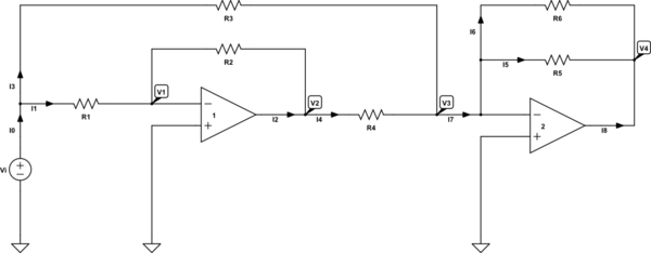
I have the following op-amp circuit:

simulate this circuit – Schematic created using CircuitLab
I know that \$\text{V}_1=0\$ and \$\text{V}_3=0\$ in the case of an ideal op-amp circuit. I wrote the following KCL equations:
$$ \begin{cases} \text{I}_0=\text{I}_1+\text{I}_3\\ \\ \text{I}_4=\text{I}_1+\text{I}_2\\ \\ \text{I}_7=\text{I}_3+\text{I}_4\\ \\ \text{I}_7=\text{I}_5+\text{I}_6\\ \\ 0=\text{I}_5+\text{I}_6+\text{I}_8 \end{cases}\tag1 $$
And the following KVL equations:
$$ \begin{cases} \text{I}_1=\frac{\text{V}_\text{i}-\text{V}_1}{\text{R}_1}\\ \\ \text{I}_2=\frac{\text{V}_1-\text{V}_2}{\text{R}_2}\\ \\ \text{I}_3=\frac{\text{V}_\text{i}-\text{V}_3}{\text{R}_3}\\ \\ \text{I}_4=\frac{\text{V}_2-\text{V}_3}{\text{R}_4}\\ \\ \text{I}_5=\frac{\text{V}_3-\text{V}_4}{\text{R}_5}\\ \\ \text{I}_6=\frac{\text{V}_3-\text{V}_4}{\text{R}_6} \end{cases}\tag2 $$
Now, I tried to LTspice to simulate this circuit for me and I used Mathematica to find the mathematical result. But they did not gave the same result. Is there a mistake in my equations?
Thanks a lot.
