0
\$\begingroup\$

I'm trying to program one ESP32 custom board with a CP2102 USB, I followed the schematic of the official datasheet but when I try to upload my code the board doesn't recieve the code but the TX led shining :

enter image description here

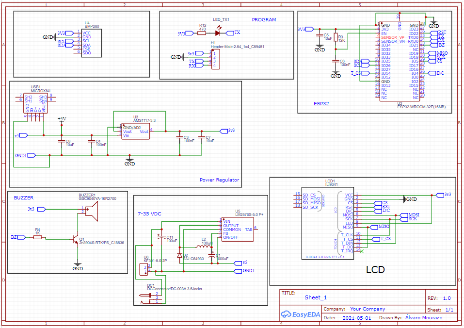
This is my schematic:

enter image description here

I tried also wiring the EN and GND pin but with the same result, and adding one 25 uF capacitor between EN and GND, does anyone have any idea where my fault is?

[![enter image description here][4]][4]

\$\endgroup\$
12
  • 1
    \$\begingroup\$ Have you measured that supply voltages are OK? Have you verifed that the devices you have connected to ESP32 do not interfere with the boot straps? How do you even make the device to go into programming mode? Also don't connect any supply to DC jack, as the LM2576 circuit is completely wrong and can do some damage. \$\endgroup\$
    – Justme
    Commented Jul 8, 2021 at 7:35
  • \$\begingroup\$ aside from the problem, you shouldn't place the ESP32 that way. the antenna shouldn't be placed near PCB tracks or power planes or any kind of copper as mentioned in the hardware design guide of espressif. \$\endgroup\$ Commented Jul 8, 2021 at 7:37
  • \$\begingroup\$ Is there a boot button on the board? On my ESP-modules there is one. I need to press it to allow the connection. \$\endgroup\$
    – Bart
    Commented Jul 8, 2021 at 7:58
  • 1
    \$\begingroup\$ @mourazo no the whole output circuit of the smps is incorrectly connected, it will not output 5V and if you had something connected there is a possibility that input voltage is connected to 5V node via capacitor, just compare your schematic with the datasheet schematic. \$\endgroup\$
    – Justme
    Commented Jul 8, 2021 at 8:22
  • 1
    \$\begingroup\$ EN is the reset pin. You need to pull IO0 low to put the esp32 into boot mode. Refer to the esp32 devkitC schematics. Your psu layout is not good. Place the chip closer to the diode, inductor and capacitors. \$\endgroup\$
    – Kartman
    Commented Jul 8, 2021 at 13:29

1 Answer 1

1
\$\begingroup\$

I solved it yesterday, I needed to put a jumper on the EN and GND pins and immediately after put a jumper on GPIO0 and GND, after that, the code was loading without problems. For the next designs I will put EN and RESET buttons. Thanks everybody

\$\endgroup\$
1
  • \$\begingroup\$ You could also use the esp-prog programmer. It saves you the cp210x, cost, power and space. + for finding out yourself. Well done. \$\endgroup\$
    – RemyHx
    Commented Dec 29, 2022 at 11:02

Your Answer

By clicking “Post Your Answer”, you agree to our terms of service and acknowledge you have read our privacy policy.

Not the answer you're looking for? Browse other questions tagged or ask your own question.