2
\$\begingroup\$

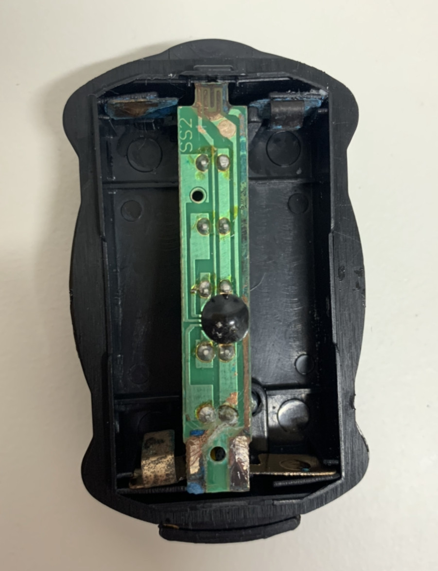
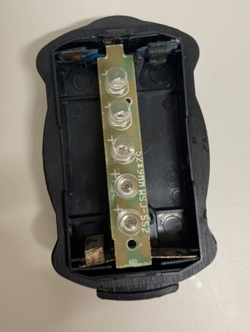
I have an old headlamp that I've been trying to fix - it takes 2 AAA batteries and doesn't work even with new batteries. I opened the headlamp up to see if I could figure out what was wrong. When I connect positive and ground to the soldered pins of each LED individually, they all light up. I can't seem to figure out how to get all of them to light up at the same time. In other words, I can't figure out how this circuit is wired.

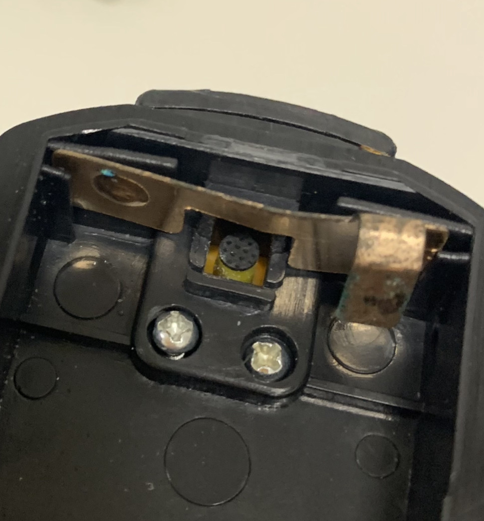
In one of the pictures, I show I a close-up of the button. It is a rubber button that simply taps on one side of the circuit (I assume it is coated in something conductive.) I'm relatively inexperienced with electronics and I would appreciate it if someone could help me understand this board. I suspect the corroded metal has caused problems, but I'd still like to see how it works.

Also, I'm not sure what the chip-on board-does.

underside of circuit

face of circuit

close up of button

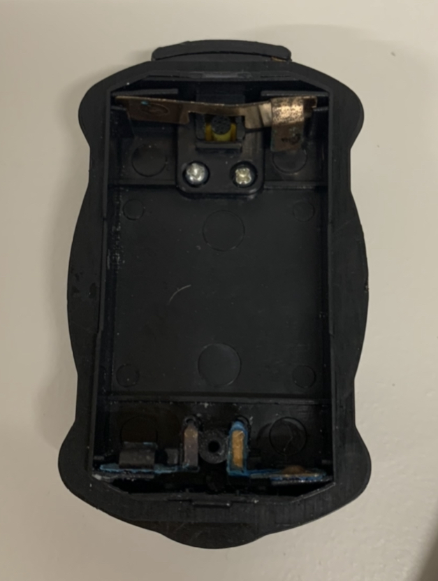
case without circuit inserted

\$\endgroup\$
1
  • 2
    \$\begingroup\$ Use a Qtip soaked in vinegar to clean the contacts. Probably this is garbage though. \$\endgroup\$
    – Kyle B
    Commented Jul 18, 2021 at 1:13

2 Answers 2

3
\$\begingroup\$

It does look rather decroded. The magic chip on board seems to control each led. If it is damaged, then no led action. I’d suggest the board may be damaged beyond repair unless you want to spend an inordinate amount of time to repair the copper tracks only to find the chip has failed. At the price point of the unit, you could harvest the leds for your own experiments and toss the rest. Then go to the $2 shop and buy another.

\$\endgroup\$
4
  • 1
    \$\begingroup\$ The chip on blob is unlikely to have gone bad. It's clearly copper trace being ate through. \$\endgroup\$
    – Passerby
    Commented Jul 18, 2021 at 1:48
  • 2
    \$\begingroup\$ No doubt about the copper being eaten. If the decrosion has gone underneath the epoxy, then the chances of repair are getting slimmer. Not to say it can't be done as I've resurrected many things in a similar or worse state. It comes down to effort vs reward. \$\endgroup\$
    – Kartman
    Commented Jul 18, 2021 at 3:17
  • 1
    \$\begingroup\$ You are using the word "decrosion", but as far as I can tell that's not a recognized word. I suggest rephrasing. \$\endgroup\$ Commented Jul 18, 2021 at 17:49
  • \$\begingroup\$ It’s a perfectly cromulent use of the word. Besides, Napoleon Dynamite used it: ‘decroded piece of crap’. \$\endgroup\$
    – Kartman
    Commented Jul 18, 2021 at 21:20
3
\$\begingroup\$

Nice effort with photos
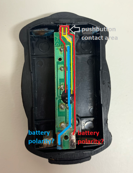
Some copper paths on the printed circuit board appear corroded. Each should be checked with a continuity tester, or an ohmmeter to see that they're continuous. And the pressure contact to the battery terminals is a suspect joint as well.
Am unsure of battery polarity. Be aware that if we guess polarity wrong, the controlling chip is instantly toast.

Typically, when you apply battery power, nothing happens - no lights light up, and the chip idles in a "sleep" mode, pulling very little current. Only when the pushbutton shorts the printed-circuit fingers (circled in grey) does the chip activate the LEDs in some pulsing sequence....another button-press often changes pulse rate, or lights LEDs continuously...another press goes back to sleep.

  • Push switch trace is yellow
  • One battery polarity is red...perhaps +?
  • Other battery polarity is blue...perhaps -?

pcb traces in colour

\$\endgroup\$
8
  • \$\begingroup\$ This. Some wire soldered in place and it should be back to working condition. \$\endgroup\$
    – Passerby
    Commented Jul 18, 2021 at 1:45
  • \$\begingroup\$ Blue is positive red is ground. Ground trace is corroded and needs to be jumped. Battery terminals need a cleaning too. \$\endgroup\$
    – Passerby
    Commented Jul 18, 2021 at 1:48
  • \$\begingroup\$ The left battery is negative on the bottom. The right battery is positive on the bottom. The pcb you have pictured and colored is upside down of its normal layout. \$\endgroup\$
    – Passerby
    Commented Jul 18, 2021 at 1:50
  • \$\begingroup\$ @Passerby My polarity guesses are not to be trusted...am unsure of orientation of that printed circuit board when that one screw is secure. Certainly, the printed circuit fingers of that push switch must face the pushbutton. Usually, the case clearly shows battery polarity. \$\endgroup\$
    – glen_geek
    Commented Jul 18, 2021 at 2:00
  • 2
    \$\begingroup\$ By the way - this is not a headlamp, (a headlamp should use WHITE LEDS). Those are RED LEDS, so it is a tail-lamp. \$\endgroup\$
    – glen_geek
    Commented Jul 18, 2021 at 2:03

Your Answer

By clicking “Post Your Answer”, you agree to our terms of service and acknowledge you have read our privacy policy.

Not the answer you're looking for? Browse other questions tagged or ask your own question.