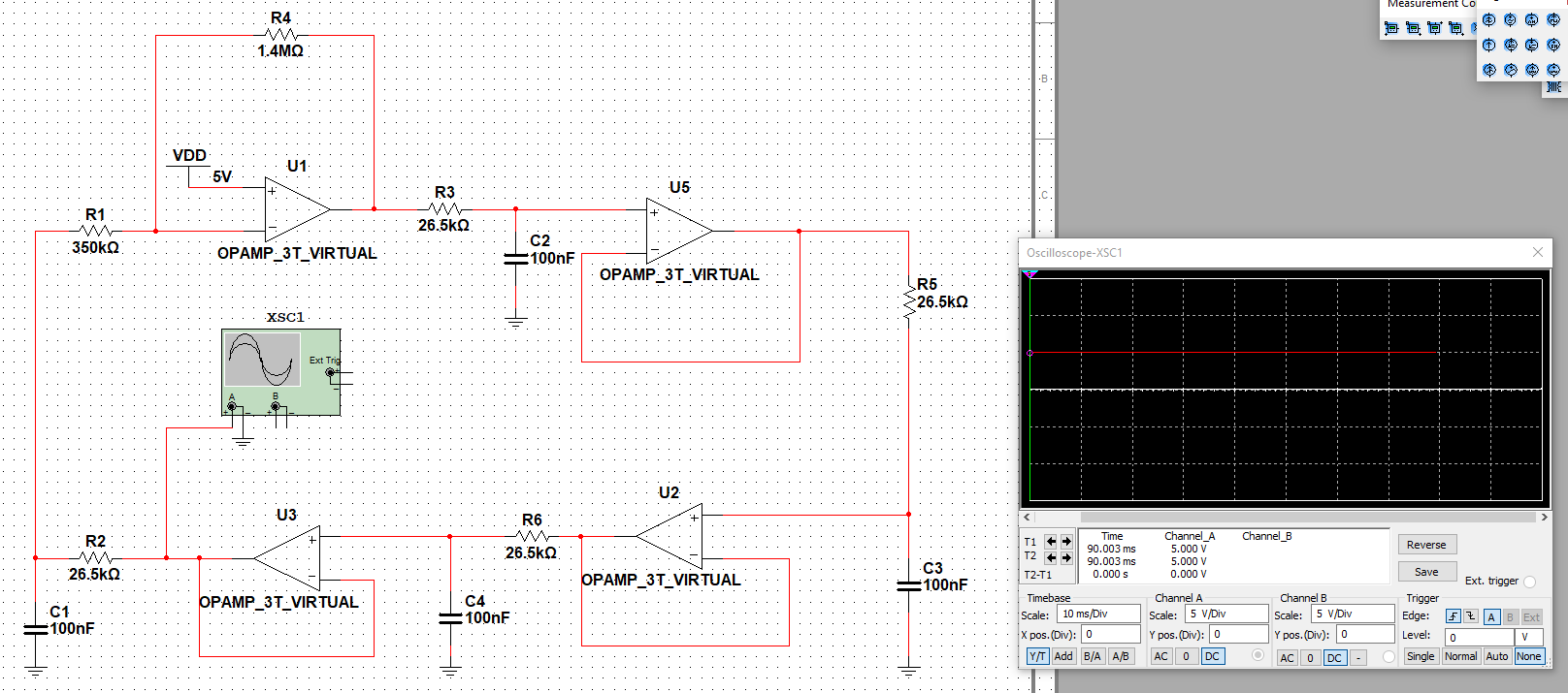
The oscillator in your question is basically a phase shift oscillator but, with op-amp buffers for each RC network. Individually, each RC produces a phase shift of 45° at the oscillation frequency and so, with four buffered RC networks you get 180° of phase shift at one particular frequency. This generally satisfies part of the Barkhausen stability criterion for an oscillator using 4 such networks and an inverting gain amplifier.
Given the values you have chosen (100 nF and 26.5 kΩ), the loss (signal out to signal in) of each network at 45° is 3.01 dB: -
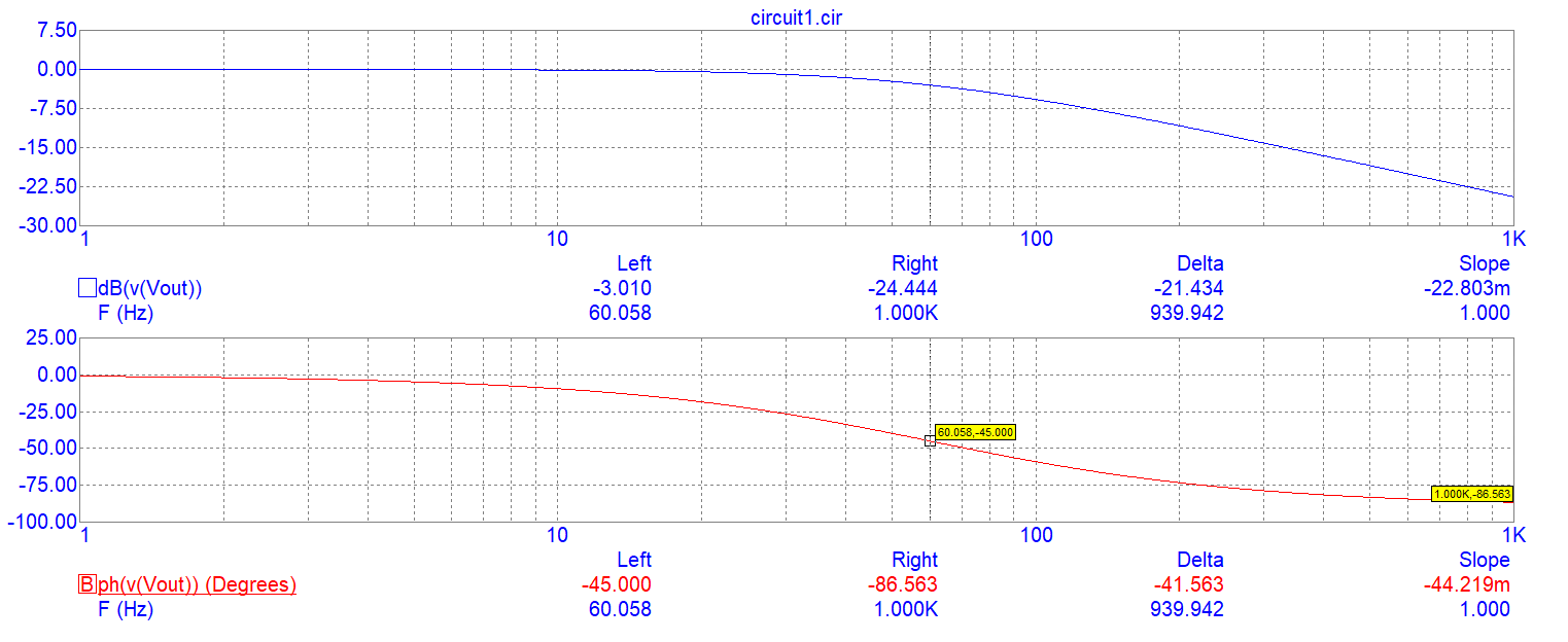
This occurs at 60.058 Hz (the intended oscillation frequency).
But, because each RC introduces voltage attenuation, you need to restore the overall gain back to greater than unity for the circuit to oscillate. Each RC has a signal loss of 3.01 dB hence, you need at least a gain of 9.03 dB in op-amp U1. In real numbers, that's a voltage gain of 4.
U1 does have a voltage gain magnitude of 1400/350 = 4 so, on the face of it it should work. However, it needs a gain higher than 4 to start oscillations. In other words you need a gain of maybe up to 4.5 to get the oscillator started. This will then fully satisfy the Barkhausen stability criterion; phase shift and overall gain are both needed for an oscillator to start and sustain oscillation.
So, try upping the gain a bit but, be aware that your sinewave will be distorted once the oscillation properly begins because the gain should be reduced back to exactly 4 for sustaining a fairly undistorted waveform. This is a general problem with some web-based tutorials; they look good but, they aren't that practical without extra effort and an additional circuit that controls gain.
There are examples where the oscillator works, but I cannot figure out
how.
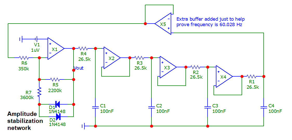
Quite simply, U1 in that link has a gain of 1500/360 = 4.166667. The devil is in the detail in a lot of electronics. So, here's a simulation in micro-cap 12 and please note, that I have used ideal op-amps with an open-loop gain of 1 million AND, to get the simulation running properly, I've offset one of the op-amp inputs (X1) with 1 μV (V1): -
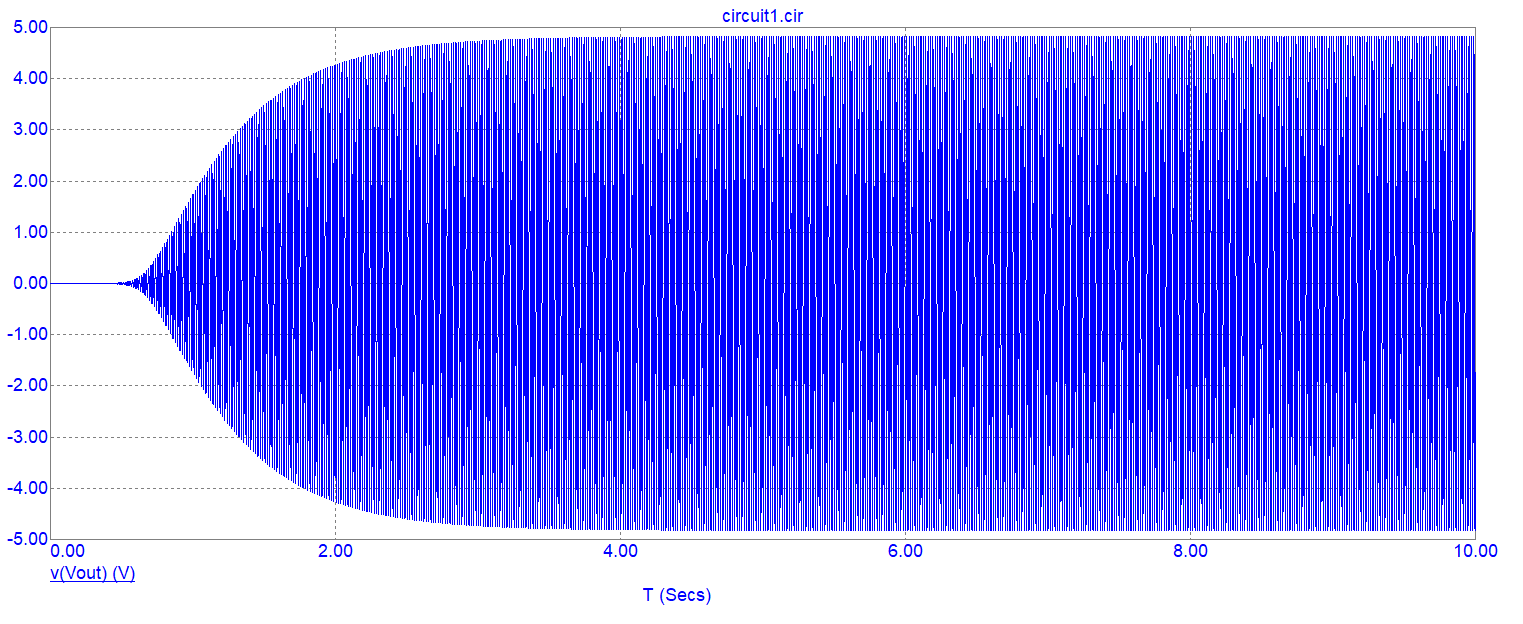
Transient start-up oscillations: -
Focus on period after about 8 seconds: -
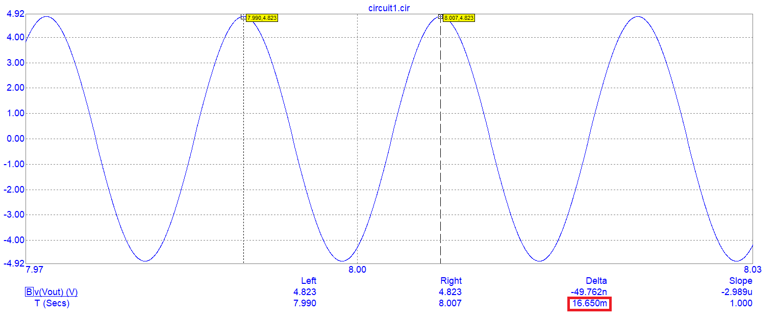
The period is 16.660 ms or 60.024 Hz (predicted to be 60.058 Hz). If I make the open-loop op-amp gain 100 million, I get an oscillation frequency of 60.0565 Hz.

