The board is rated for a peak current of 30A, not continuous driver current of 30A. The continuous drive current spec'd is 14A.
In section 4 of the datasheet for the motor driver, it has the package and thermal dissipation information for the driver.
Figure 40 shows the junction-ambient thermal resistance of the board in natural convection (i.e. no fans). The board itself has roughly an area of \$3.5cm \cdot 6cm = 21cm^2\$, which is shared between the two motor drivers. For the sake of simplicity, let's assume that we only have 1 driver running, and we only get an effective ~\$15cm^2\$ of PCB heat sinking (close to the max values shown in the plot). At this level we have the following junction-ambient thermal resistances:
\$
R_{thHS} = 28 \frac{C}{W}\\
R_{thLS} = 26 \frac{C}{W}\\
R_{thHSLS} = R_{thLSLS} = 7.5 \frac{C}{W}
\$
The temperature rises above ambient is then given in table 15. For this example, let's assume we're driving HSA and LSB, and we're analyzing \$T_{jHSAB}\$ (junction temperature rise of the high side gates).
\$
T_{jHSAB} = P_{HS} \cdot R_{thHS} + P_{LS} \cdot R_{thHSLS} + T_{amb}
\$
Now let's refer to the electrical characteristics of device. The MOSFET gates can be modeled as resistors when on, with the following resistance values:
\$
R_{HS} = 28 m\Omega\\
R_{LS} = 10 m\Omega\\
\$
The power dissipation of a resistor given a current:
\$
P = I^2 \cdot R
\$
So re-writing the junction temperature rise equation, we get:
\$
T_{jHSAB} = I^2 \cdot R_{HS} \cdot R_{thHS} + I^2 \cdot R_{LS} \cdot R_{thHSLS} + T_{amb}
\$
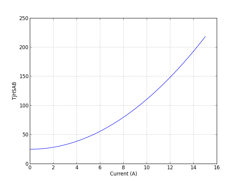
Plotting this vs. current, we get:

At ~12A of continuous drive we've exceeded the allowable thermal junction of the chip. At this current, A rough heat dissipation calculation for the driver chip is:
\$
P_{d} = I^2 \cdot R_{HS} + I^2 \cdot R_{LS} = 5.47W
\$
In addition to these calculation, DC motors don't have a constant current consumption. Rather, as the motor gets faster it generates a back EMF which will decrease the current flowing through the motor until the motor reaches the no load speed and consumes near 0 current. Maximum current is consumed at stall (reason why stalling DC motors is bad). Maximum mechanical power occurs at half the no-load speed.
So let's assume we're driving a motor with 16V and we want maximum mechanical power. Let's say for sake of argument this results in 12A flowing through the circuit. At half speed we get an 8V back EMF, resulting in a maximum mechanical power of (assuming 100% efficient motor):
\$
P_M = (16V - 8V) \cdot 12A = 96W
\$
So as you can see the mechanical motor power is significantly higher than the heat losses of the motor driver.

