0
\$\begingroup\$

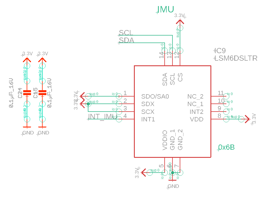
So I designed this custom PCB with a ESP32 and an IMU ST LSM6DSL over i2c. Everything is running at 3.3V.

However, when I initialise the IMU in the firmware and start reading it in normal mode at 104Hz (which is much lower than the 6.6kHz it can do), the IMU gets really hot after a minute!

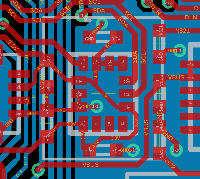
I carefully checked the hardware: every pin is as it should be according to the datasheet. There ways no layout example in it (or on the product page) though so I did the best I could in my busy layout.

Any idea why it does that? Has anyone experienced similar issues, maybe with one of the other IMUs from the ST family? (LSM6DSM, LSM6DSO, LSM6DSOX, LSM6DS33, ISM330DLC, etc).

Here's a screenshot of my schematic and layout. Shall I increase the trace width or the value of the capacitors? Or is the problem purely in firmware?

Thanks all

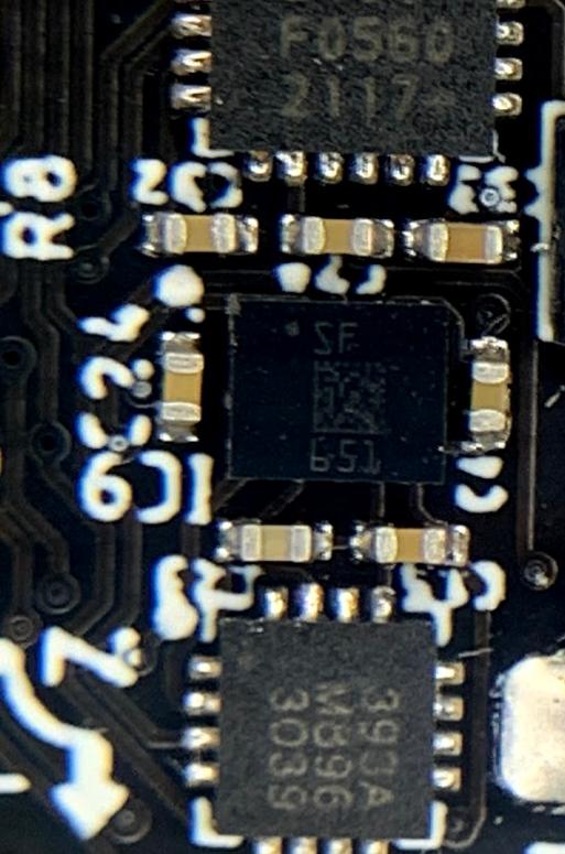
enter image description here enter image description here enter image description here

\$\endgroup\$
5
  • 1
    \$\begingroup\$ I think you have a damaged IC. A functioning IC like is incapable of getting hot. Probably a short or partial short somewhere. \$\endgroup\$
    – DKNguyen
    Commented Aug 12, 2021 at 17:55
  • 1
    \$\begingroup\$ That or, something is oscillating which shouldn't be. 'Scope around. \$\endgroup\$
    – rdtsc
    Commented Aug 12, 2021 at 17:56
  • \$\begingroup\$ In MCU family other than ST, have seen power-up sequencing cause problems, where peripherals manage to power up first and drive one or more MCU pins high (before the MCU Vdd has risen properly). The result was latch-up, which causes all manner of strange behaviour, one possibility is over-heating. It is also possible that some internal MCU modules having independent DC supplies can cause latch-up, if their supply rises early (or late?). \$\endgroup\$
    – glen_geek
    Commented Aug 12, 2021 at 18:31
  • \$\begingroup\$ DKNguyen: I've got a dozen boards (90%) that get hot, so it's most likely not a faulty IC, but thanks for the suggesstion. @glen_geek: Interesting suggestion, I use a ESP32 MCU that is quite slow to boot. What could I do to avoid this latch-up situation? Other than having a load switch somehow that enables the IMU 3.3V rail after the MCU has booted? \$\endgroup\$
    – coriv
    Commented Aug 12, 2021 at 20:01
  • \$\begingroup\$ You say all chips are powered from the same 3.3V Vdd? That would seem safe. You're a bit close to the maximum recommended Vdd of 3.6V, but reasonably far below the absolute max of 4.8V. You should check that a turn-on transient doesn't cause a Vdd overshoot of these values, even momentarily - a careful 'scope probing should be done close to this chip. \$\endgroup\$
    – glen_geek
    Commented Aug 13, 2021 at 0:03

2 Answers 2

0
\$\begingroup\$

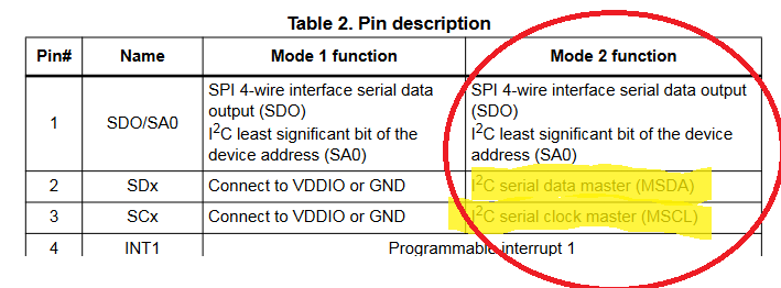
My 'guess' is you may have an output tied high if you are using mode 2 function (AFAIK it looks to be mode 2). If so then if pin 2 or 3 are driven low to ~0V and tied to 3.3V this would sink a lot of current and heat the part.

enter image description here Source: https://www.st.com/content/ccc/resource/technical/document/datasheet/ee/23/a0/dc/1d/68/45/52/DM00237456.pdf/files/DM00237456.pdf/jcr:content/translations/en.DM00237456.pdf

If so you could pull the part off and cut the traces to 3.3V (and probably you'd want to install a new part)

\$\endgroup\$
3
  • \$\begingroup\$ Interesting, but I was under the impression that I use Mode 1, since I don't connect any other sensors to the IMU. The IMU is a slave in my setup, and is connected to the pins SDA and SCL. What is the difference between Modes 1 and 2 and can the chip be configure to Mode 1? \$\endgroup\$
    – coriv
    Commented Aug 12, 2021 at 19:59
  • \$\begingroup\$ CS (I believe) determines the mode (but I'm only 95% sure due to the wording in the datasheet). Now that I'm looking at it again, it appears that tying pin 1 to 3.3V would probably be a bad thing, because in most cases I2C busses have open drain (low side FETS), if the open drain is turned on you essentially get a short and heating. \$\endgroup\$
    – Voltage Spike
    Commented Aug 12, 2021 at 22:16
  • \$\begingroup\$ @coriv Mode 1 is default. You can activate i2c passthrough mode in master config register. Did you activate it by mistake in your code? \$\endgroup\$
    – Rokta
    Commented Aug 13, 2021 at 7:10
0
\$\begingroup\$

Ok it looks like I solved the problem by leaving the pins 2 (SDx) and 3 (SCx) floating. I still don't fully understand why the datasheet specifies to tie them to GND or VCC since I am in Mode 1, but anyway, thanks everyone for your answers!

\$\endgroup\$

Your Answer

By clicking “Post Your Answer”, you agree to our terms of service and acknowledge you have read our privacy policy.

Not the answer you're looking for? Browse other questions tagged or ask your own question.