0
\$\begingroup\$

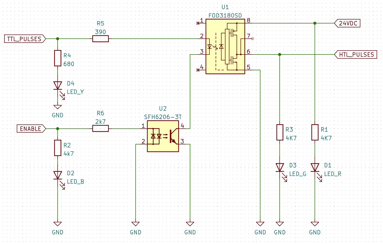
I've built a circuit that helps me translate TTL pluses coming from an rotary encoder into HTL pulses needed for another device.

I use a FOD3180 to get a push-pull output and a SFH6206-3T that allows me to enable/disable the output pulses.

enter image description here

As soon as I connect the 24VDC the FOD3180 starts getting hot until it dies. I looked into the datasheet but cannot figure out why that happens.

\$\endgroup\$
5
  • 1
    \$\begingroup\$ Not sure if it's your problem but you are very close to the 25V absolute maximum supply voltage. Maybe higher depending on what your "24V" actually is with tolerance, ripple, transients etc. Maximum recommended is 20V (minimum 10V). \$\endgroup\$ Commented Oct 20, 2021 at 10:09
  • 1
    \$\begingroup\$ Using two opto isolated circuits with a single GND is a total nonsense. Also it is a nonsense to use a gate driver that usually works on 15V and connect a 24V supply on it, hence the absolute max. rating is 20V. \$\endgroup\$ Commented Oct 20, 2021 at 10:11
  • \$\begingroup\$ Ok, I just saw the 25V Absolute maximum in the datasheet ant thought 24V might be ok. Any recommendatiosn what IC to uase as an alternative? I prefer a single chip over a circuit built out of multiple parts ... \$\endgroup\$
    – Bouni
    Commented Oct 20, 2021 at 10:57
  • \$\begingroup\$ Note that U2 seems like it could just be a transistor. The optocoupler is overkill because there is no isolation anyway. In fact you can make this whole circuit without any optocouplers. \$\endgroup\$ Commented Oct 20, 2021 at 11:11
  • \$\begingroup\$ I feel like I've been writing this a lot lately - "Absolute Maximum Ratings" are not an operating spec! The datasheet tells you that right there: "The device may not function or be operable above the recommended operating conditions and stressing the parts to these levels is not recommended. ... The absolute maximum ratings are stress ratings only.". Please stop abusing your components and ignore the "Absolute Maximum Ratings" section in datasheets in future. \$\endgroup\$
    – brhans
    Commented Oct 20, 2021 at 11:34

1 Answer 1

0
\$\begingroup\$

There is no required 100nF bypass capacitor for stability. It might be unstable and oscillate. Datasheet says it must be connected.

Also the chip has recommended voltage range up to 20V. The 24V exceeds this and is very close to the 25V absolute maximum rating. Basically, the recommended range is exceeded so the chip does not need to work outside recommended 20V supply. This is mentioned in the datasheet as well.

\$\endgroup\$

Your Answer

By clicking “Post Your Answer”, you agree to our terms of service and acknowledge you have read our privacy policy.

Not the answer you're looking for? Browse other questions tagged or ask your own question.