8
\$\begingroup\$

For a one-off hobby project I want to add a potentiometer to an existing two-sided PCB. There is an unpopulated zone (as far as I can tell) on the PCB that looks ideal, but I'd have to drill mounting holes. The more I read about drilling holes in PCBs and the tools I'd need and making sure it doesn't short out anything, etc... the more I start to wonder whether I should just cut the pins and mounting clamps of the potentiometer short, and glue the four green plastic legs to the PCB.

Am I right in thinking that for someone who doesn't even have a drill press for their Dremel, using a bit of epoxy resin glue would be the easier option, and give basically the same result?

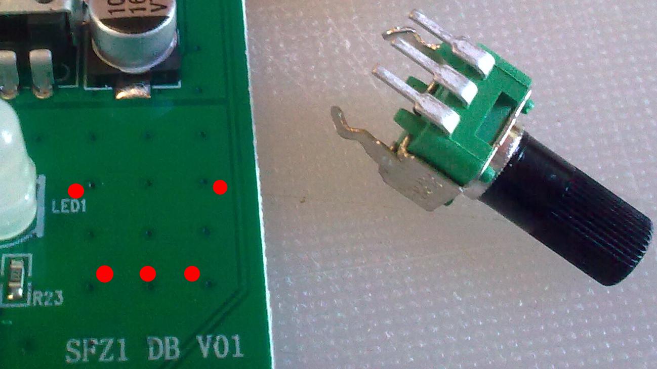
PCB with hole locations marked

\$\endgroup\$
15
  • 4
    \$\begingroup\$ You can easily drill a hole through a PCB manually with a twist drill and a 1/16" drill (I prefer an V-tip engraving bit though). But if there are inner layers then the problem with drilling is that unless you insert bushings you can't guarantee the inner layers wont' touch the pins. This applies to outside layers too but at least on outside layers you can twist a countersink or some other tool to abrade away the copper around the hole. \$\endgroup\$
    – DKNguyen
    Commented Aug 28, 2021 at 2:52
  • \$\begingroup\$ @DKNguyen Afaik it's a single layer board printed on both sides. It's quite a simple design, but there is obviously copper (ground?) on both sides everywhere in the location where I'd have to drill the holes. \$\endgroup\$ Commented Aug 28, 2021 at 2:55
  • 1
    \$\begingroup\$ If both layers on both sides are both the ground layer you can just drill holes for the mechanical support pins on the pot. Then you can either bend the signal pins or drill oversize holes for the signal pins so they cannot touch the edges and solder wire directly to the signal pins. You can use burnishing pen (looks like a eraser pen but with a fiberglass brush insert) to abrade away the solder mask so you can solder the mechanical support pins to the copper. \$\endgroup\$
    – DKNguyen
    Commented Aug 28, 2021 at 2:55
  • 1
    \$\begingroup\$ Well you don't need to find out if they are the ground layer as much that you need to find out that they are the same layer. \$\endgroup\$
    – DKNguyen
    Commented Aug 28, 2021 at 3:00
  • 1
    \$\begingroup\$ In that case, I would bend the leads carefully with needle nose pliers so they don't contact the solder mask and glue the part down directly. Attach AWG 30 insulated wires to the pins to make the connections. \$\endgroup\$ Commented Aug 28, 2021 at 3:32

2 Answers 2

6
\$\begingroup\$

One problem is even if drilling holes you may short the pins to the plane, you would have to have some way to isolate the pins from the metal on the plane if you were to drill holes. It would also be difficult if this were four layer board to determine if there were additional signals or planes running in between the top and the bottom layer.

I think a good way to attach the pot to the PCB would be to bend the pins so that you could mount the bottom of the pot flat with the PCB. Then use epoxy to glue the pot down to the PCB.

You could then solder jumper wires to the pins.

\$\endgroup\$
1
  • 3
    \$\begingroup\$ As far as I can tell it's just a one-layer two-sided board. It's a very simple circuit. Someone suggested putting shrinkwrap around the pins before putting them through the holes. But I'm leaning towards only drilling holes for the support pins anyway, not the signal pins; that would simplify things already. If I can establish that the copper layers on each side that I'm drilling through are ground, then there's no real problem in touching them with the support pins. But just gluing and not drilling is indeed looking more and more attractive to me. \$\endgroup\$ Commented Aug 28, 2021 at 6:21
6
\$\begingroup\$
  1. Bend the pot (three of) pins outward, except the two of pot body pins.
  2. scratch off the solder-mask of the ground area.
  3. Solder the body 2 pins on the peeled off ground plate.
  4. Now, wire the 3 pins to signals.
\$\endgroup\$
11
  • \$\begingroup\$ Do you mean I should solder the two mechanical support pins to the copper layer on the top surface without drilling any holes? \$\endgroup\$ Commented Aug 28, 2021 at 3:03
  • \$\begingroup\$ Yes, @YourUncleBob . Don't ! drill the board. The copper layer is strong enough to hold the pot. \$\endgroup\$
    – jay
    Commented Aug 28, 2021 at 3:12
  • 4
    \$\begingroup\$ TH to SMT conversion! \$\endgroup\$
    – crasic
    Commented Aug 28, 2021 at 3:19
  • 1
    \$\begingroup\$ @crasic "inherent artistry" is right. Though, people no more call it Artwork. \$\endgroup\$
    – jay
    Commented Aug 28, 2021 at 3:47
  • 1
    \$\begingroup\$ Peel off? You mean just scratch off the soldermask? \$\endgroup\$
    – Oskar Skog
    Commented Aug 28, 2021 at 19:05

Your Answer

By clicking “Post Your Answer”, you agree to our terms of service and acknowledge you have read our privacy policy.

Not the answer you're looking for? Browse other questions tagged or ask your own question.