0
\$\begingroup\$

So, for OpAmp stability, we don't want \$A_{OL}\beta\$ to be -1, which we can derive from the Bode plot by looking at: \$20\log(A_{OL})-20\log(1/\beta)\$ and looking at the rate of closure to indicate the phase shift I have at that point.

I understand, that \$1/\beta\$ is the noise gain, which is something different from the signal gain, well at least in the case of the inverting configuration. The default differentiator is an inverting configuration with the input resistor replaced by a capacitor.

It follows that \$\beta = \frac{X_C}{X_C+R}\$, hence my \$1/\beta(s) = 1 + sRC\$ if I inspect this in my \$s\$-domain.

This gives me a zero with a frequency of \$f = \frac{1}{2\pi RC}\$ and hence my aplitude Bode plot should be a straight line and then rise with 20 dB/dec - this will intersect my \$A_{OL}\$ which has a -20 dB/dec rolloff by the dominant pole (assuming a single pole OpAmp) and give me an unstable ROC as I have a 40 dB/dec ROC leading to a zero phase margin.

However, when I look at some application notes (e.g. TI's Handbook of Operation Amplifier Application, see screenhot) I typically see that they simply argue that the overall transfer function is a straight line with a +20 dB/dec. This is obviously correct, as: \$ \frac{u_{out}(s)}{u_{in}(s)}=-\frac{R}{X_C} = -sRC\$. And then they derive from that an unstable ROC. However, for any ROC analysis, don't I need to look at the noise gain, not my signal gain. Is this right?

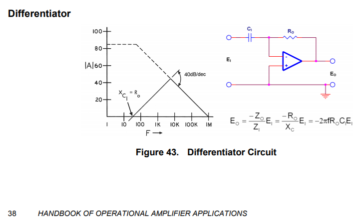
enter image description here

\$\endgroup\$
1

2 Answers 2

1
\$\begingroup\$

Yes, for loop stability you analyze the loop gain (noise gain), not the signal gain.

A differentiator may be actually unstable if there are more than 2 poles in the system. Theoretically a simple 2-pole system will be stable as the phase never reaches 180°, just asymptotically approaches it.

If there is a 3rd pole, then its phase can contribute to the total loop phase, making it reach 180° at some point where the magnitude of the gain is still > 0 dB, thus making it unstable.

\$\endgroup\$
0
\$\begingroup\$

My understanding of this is that it is the rate of closure between the open loop response plot and the noise gain plot (1/beta plot) which determines stability margins. This is the case whether the amplifier is in an inverting or non-inverting configuration.

For instance, consider a straight forward inverting amplifier with input and feedback resistances. The signal gain response will roll off as frequency increases reducing the rate of closure between its response and the open loop gain plot. If this rate of closure was to be taken as the indicator of stability margins then it would give an incorrect impression of the amplifier having higher stability margins than correctly using the rate of closure between the noise gain plot (1/beta plot) and the open loop gain plot. In this example the noise gain plot would be a horizontal line and would approach the open loop gain plot with a rate of closure of 20dB/decade, assuming a single pole amplifier.

As you have inferred in your first paragraph, stability margins are determined by the loop gain and loop phase where loop gain = beta * Aol = Aol/(1/beta) that is to say open loop gain divided by noise gain or open loop gain minus noise gain when logs of the two are taken. The phase margin is determined by considering the loop phase at the frequency where the loop gain is unity, where Aol*beta = 1 and this is the frequency where the noise gain response crosses the open loop gain response, Where Aol = 1/beta.

\$\endgroup\$

Your Answer

By clicking “Post Your Answer”, you agree to our terms of service and acknowledge you have read our privacy policy.

Not the answer you're looking for? Browse other questions tagged or ask your own question.