6
\$\begingroup\$

What is the best way to "debug" the current in a PCB?

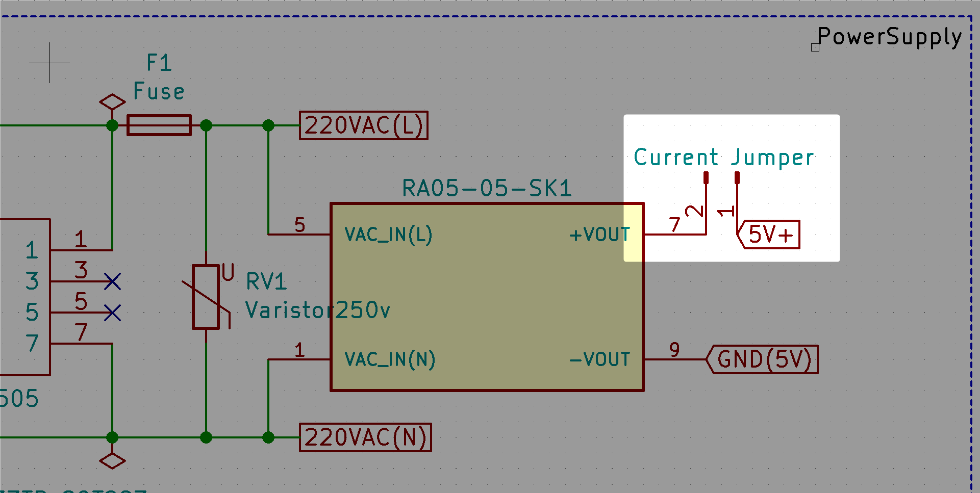
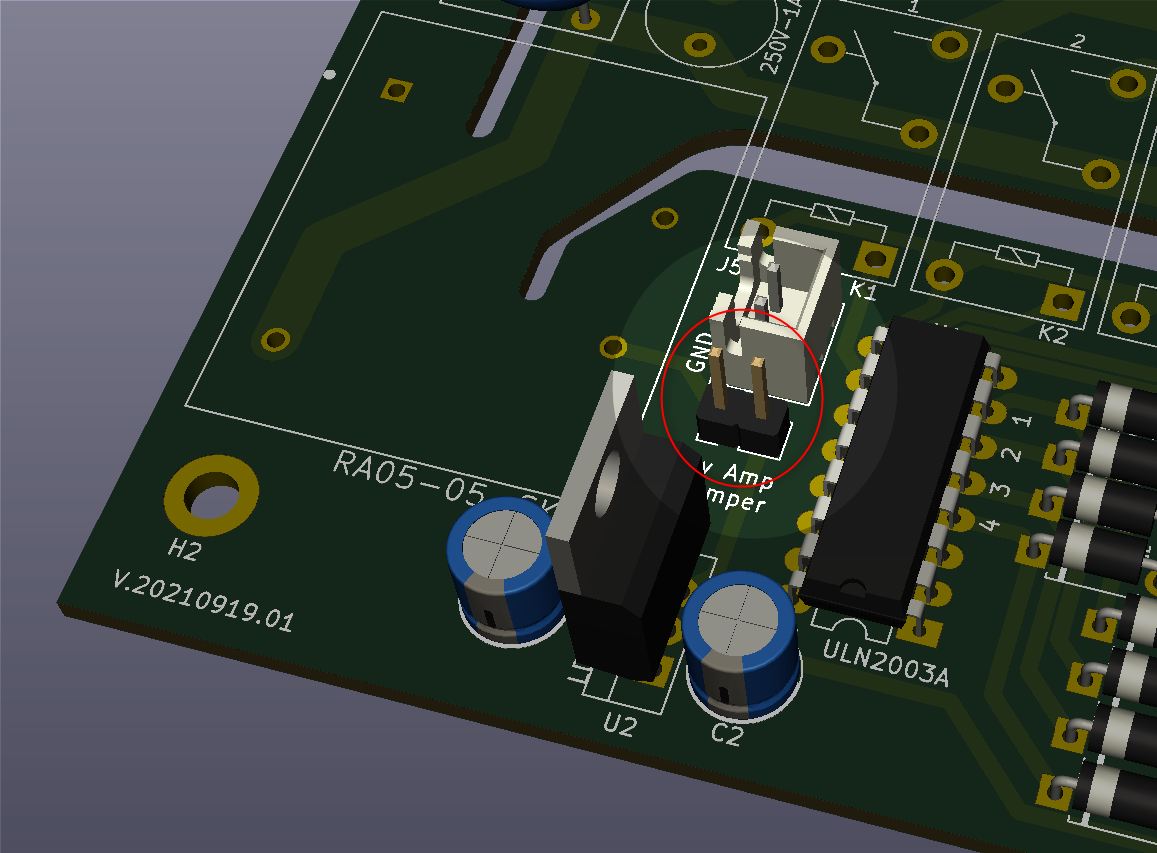
My (first!) PCB has a 220v->5v PS on it. I would like to measure how much current is using after the PS to monitor how far from the limits my circuit is.

To achieve that, I was thinking on adding jumper pins, to be able to attach a multimeter. Is there a better way of doing that?

enter image description here enter image description here

\$\endgroup\$
2
  • \$\begingroup\$ Ideally, you should be able to calculate the required current from the design so that you specify the correct size of PSU to begin with. This seems like a backwards way of designing... guess and check is not the best approach here. \$\endgroup\$
    – J...
    Commented Sep 21, 2021 at 18:02
  • \$\begingroup\$ If you need to measure current over time, consider using an oscilloscope, a series resistor and an opamp device e.g. the uCurrent Gold. eevblog.com/product/ucurrentgold \$\endgroup\$
    – Michael
    Commented Sep 21, 2021 at 18:23

2 Answers 2

5
\$\begingroup\$

In addition to the first answer, if it is important in production you may consider the permanent addition of a TS1100 Uni/Bidirectional Current-Sense Amplifier and a good shunt resistor to give you a direct measurement of voltage across the shunt resistor and consequently the actual current, all with great accuracy. There's even a demo board that you can very quickly wire-in, and with a standard voltmeter or oscilloscope, you can measure the PS current as required.

\$\endgroup\$
1
  • \$\begingroup\$ This is great! I am still hammering my head around it to fully understand. but it looks really good! Thanks a lot! \$\endgroup\$ Commented Sep 23, 2021 at 10:28
9
\$\begingroup\$

Add a low value current sense resistor in series with the output from the 5V supply, and then measure the voltage across it to determine current. In other words, do it the same way your multimeter does (it measures current internally by looking at the voltage drop across a low value resistor.)

Later on, in 'production', you can replace the shunt resistor with a shunt. (If this is important, and current margins allow, pick a standard case size so you can put a 0ohm resistor in there later.)

If you want to bring the ends of the resistor out to a connection, use a separate pair of tracks to make a kelvin connection as directly to the pads of the resistor.

Generally test points aren't brought out to headers like that, but to little pins like this which you can clip a lead to. I'm no expert, however, in PCB design. If you have a ready made lead to connect a header to your multimeter (in voltage mode) go ahead and use a header. But if people will be clipping leads to it, clipping two test probes to a 0.1" pitch header is quite hard.

Note that what you're proposing will work, but has quite a few disadvantages:

  • When measuring it adds long wires in series with the output of the psu. This will change the regulator's inductive load and may effect performance, or even cause oscillation.
  • All the current has to go through that tiny little header.
  • All the current has to go through a tiny little header shunt when you're not measuring.
\$\endgroup\$
4
  • 1
    \$\begingroup\$ @Carlos Garcia from that (out of perspective) photo I do wonder if you've got enough clearance between the mains and LV sides of the board, particularly if you're going to be leaving test leads hanging off things. \$\endgroup\$
    – 2e0byo
    Commented Sep 21, 2021 at 8:50
  • \$\begingroup\$ @JRE: thank you, I will start writing x V properly, sorry. \$\endgroup\$
    – 2e0byo
    Commented Sep 21, 2021 at 8:51
  • \$\begingroup\$ Thanks @2e0byo. I am looing for something I can "leave there" for production as well :) - And thanks for the clearance notice!! The closes point between mains and 5v is 7mm apart. All the things around the jumper are 5v or 3.3v \$\endgroup\$ Commented Sep 21, 2021 at 9:00
  • \$\begingroup\$ Actually, looking at it again, if your PSU is a potted module you're probably fine. More clearance doesn't hurt, though, if you can fit it in. You can leave a sense resistor for production, although it will likely be cheaper to replace it with an equivalent sized 0ohm resistor. \$\endgroup\$
    – 2e0byo
    Commented Sep 21, 2021 at 9:05

Your Answer

By clicking “Post Your Answer”, you agree to our terms of service and acknowledge you have read our privacy policy.

Not the answer you're looking for? Browse other questions tagged or ask your own question.