I am figuring out how we can interface the flow meter to our controller before moving onto the software part. I have never worked with a 4-20mA interface hence just looking for some advice.
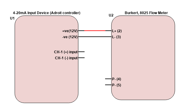
Below shows the connection diagram.

I am able to power the flow meter via the 12 V supply from our controller. The P- and P+ is the pulse output but that's not what we are looking to use.
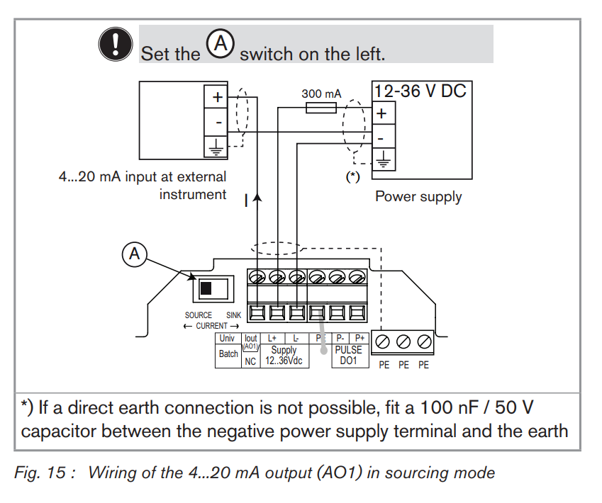
The CH-1 is the input channel that needs the 4-20mA output from the sensor to be fed. Where can I find this output on the flow meter or how do I go about the connection from an electrical point of view, with reference to the above sketch?
Here is the datasheet/manual for the sensor.
Any insights would be appreciated. Thank you.

