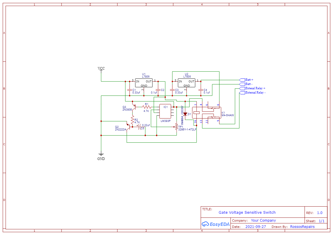
So I have designed this circuit to operate a relay in an off grid circuit. When the solar panel charges the battery over 12.9 V the relay is supposed to kick in. But from 12.8 V to 13 V the relay buzzes on and off. I have tried a few times to fix the issue but the best I have gotten is slow the buzz down with a capacitor in parallel with the relay. Any thoughts?
-
4\$\begingroup\$ Might be nice if you could draw the schematic so we can read it without mental acrobatics. You have no hysteresis. The datasheet for the comparator should have examples. \$\endgroup\$– KartmanCommented Sep 28, 2021 at 8:42
-
3\$\begingroup\$ As well, D1 is backwards. \$\endgroup\$– KartmanCommented Sep 28, 2021 at 8:43
-
2\$\begingroup\$ Look here for some hints to help you draw a more accessible schematic: electronics.stackexchange.com/questions/28251/… \$\endgroup\$– BimpelrekkieCommented Sep 28, 2021 at 8:54
-
\$\begingroup\$ Something like a 555 or a TL431 might be a better choice. Even a zener diode and the relay might just do the job. \$\endgroup\$– KartmanCommented Sep 28, 2021 at 11:11
2 Answers
But from 12.8v to 13v the relay buzzes on and off.
The problem is likely this; when the relay is activated the current drawn from the solar panel causes a drop in its supply voltage and this then causes the LM393 to deactivate the relay. That deactivation means less current from the solar panel hence the voltage rises a bit and, the LM393 then retriggers and you are going round in a circle until the voltage rises sufficiently on the panel that it doesn't drop below the LM393 threshold voltage when the relay gets activated.
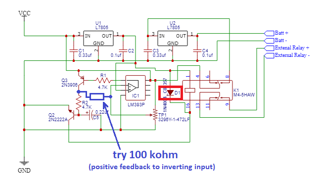
As others have pointed out, D1 appears to be the wrong way round in your schematic: -
I've also added a resistor that creates hysteresis and the value of 100 kΩ might be enough to avoid the problem of the relay buzzing in that when the output of the LM393 switches, it adjusts the target threshold for the comparator a bit.
Please try and use the right symbol for the LM393 rather than just a box with connections and no pin numbers. It would also help if you positions BJTs so that they were more logically drawn (Q2 for instance).
When the inputs of the comparator are close in potential, any noise appearing on those inputs (including power supply noise due to the relay switching) can change which input is greater, and that of course will cause the output to change state.
I think this is what is causing your relay to chatter.
Part of the solution is to ensure that the inputs are as noise free as possible, with power supply decoupling capacitors and wotnot, but the go-to solution in most applications is to employ hysteresis:

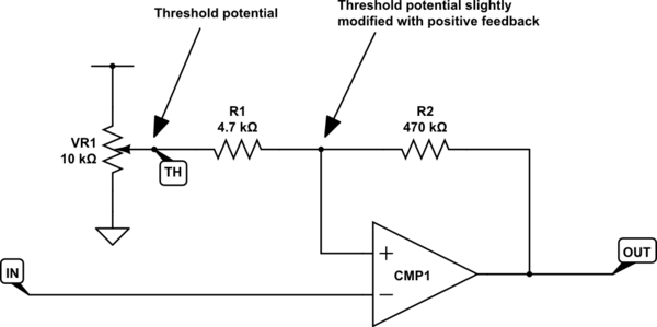
simulate this circuit – Schematic created using CircuitLab
As you seem to do in your circuit (which is very difficult to understand from that terrible schematic), I provide a threshold voltage \$V_{TH}\$ by setting the position of VR1. This voltage defines some "centre" to be compared against \$V_{IN}\$. If TH were tied directly to the non-inverting input of the comparator CMP1, then its output would be dependent only upon \$V_{IN}\$ and \$V_{TH}\$.
Here, though, I've inserted a potential divider consisting of R1 and R2 between TH and OUT, which superposes onto \$V_{TH}\$ a small adjustment dependent upon the current state of the output.
This feedback causes the switching threshold to be reduced slightly when the output is low, and increased when the output is high. It is positive feedback, which creates input hysteresis, and the circuit is a form of Schmitt Trigger.
A couple of advantages of hysteresis are:
Improved immunity to input noise. The dynamic threshold means that input fluctuations must exceed the change in threshold levels, to cause a change in output state.
Output transition is faster. When some input condition causes the output to begin to change state, this changing output also causes the difference in comparator input potentials to increase, reinforcing the condition that began the transition in the first place, and driving the output harder towards its new state.
It remains to choose suitable values for R1 and R2, to obtain an acceptable degree of hysteresis for this application.


