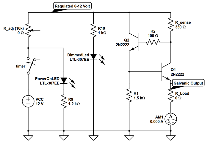
I am running this cheap ammeter on a NPN transistor based current limiter. When I attempt to power the ammeter via the same power supply as the current limiter, the voltage across the current limiter drops and I get a slight current through the ammeter. When I use an external 12 volt supply the system begins to behave normally, and I get zero current through the ammeter and around 12 volts across the current limiter when it is an open circuit (R_load = inf.) I imagine the cheap ammeter allows some current to flow through it when it is grounded to the same circuit.
\$\begingroup\$
\$\endgroup\$
4
-
\$\begingroup\$ Do you have a datasheet for this ammeter? If so, what does it say about isolation between its power supply and sense input? \$\endgroup\$– nanofaradCommented Oct 17, 2021 at 22:00
-
1\$\begingroup\$ This is not an active current limiter circuit. Q2 and R1 should be in opposite locations with some other changes \$\endgroup\$– D.A.S.Commented Oct 17, 2021 at 22:26
-
\$\begingroup\$ en.m.wikipedia.org/wiki/Current_limiting These are different current limiters. \$\endgroup\$– D.A.S.Commented Oct 17, 2021 at 22:30
-
\$\begingroup\$ @TonyStewartEE75 I accidentally implemented the version for PNP transistors with NPN transistors. thanks for the comment \$\endgroup\$– OscarCommented Oct 17, 2021 at 22:53
Add a comment
|
1 Answer
\$\begingroup\$
\$\endgroup\$
I found the solution to my problem. The cheap ammeter only works when it is on the ground side of the circuit. I tried connecting it before the load and that is why it did not work. I think the ground for the current sensing and power leads on the ammeter must be common or something like that.


