0
\$\begingroup\$

I have a seven segment display with 14 pins on each side and three digits. The display include a decimal point. However, I'm struggling to figure out the function of each pin. This item is described as a "3-digit Common-Cathode Display". enter image description here
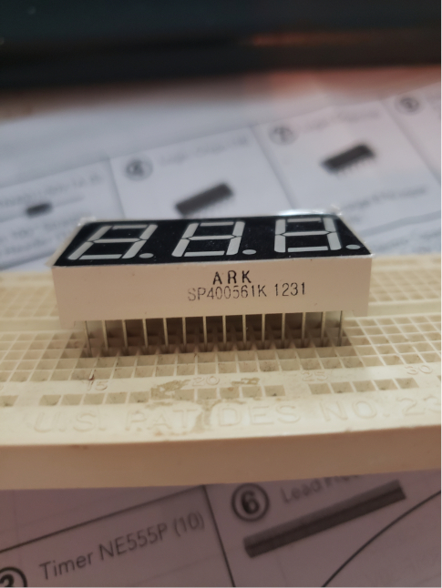
I'm struggling to find the purpose of each pin. 28/3 is not an even number, so I assume all the pins......share the cathode. However, each segment has 8 L.E.D.s on it, so I don't know why I would has 4 extra pins or how to determine which ones are shared.

Can anyone help me with this? Also, not sure how to check what kind of voltage/resistors it needs, I can't find a data sheet. It's old.

\$\endgroup\$
2
  • 3
    \$\begingroup\$ how about checking with a multimeter in diode test mode? \$\endgroup\$
    – FrancoVS
    Commented Oct 27, 2021 at 17:58
  • 1
    \$\begingroup\$ Here are a pair of datasheets for 28-pin 3-digit displays: #1, #2 and this seems to be a common pinout. (7 pins for display segments, 1 pin for the dot 1 pin for common-cathode) x 3 digits == 27 pins. So only 1 'spare'. \$\endgroup\$
    – brhans
    Commented Oct 27, 2021 at 18:05

1 Answer 1

2
\$\begingroup\$

You can use a DMM in Diode mode to find which segment is connected where.

Or, you can check the datasheet. It is a generic part from multiple vendors. Here is one option.

\$\endgroup\$

Your Answer

By clicking “Post Your Answer”, you agree to our terms of service and acknowledge you have read our privacy policy.

Not the answer you're looking for? Browse other questions tagged or ask your own question.