I am measuring 250VAC with an ACS37800. It happens to be a PWM based output of a TRIAC. For testing purposes, I am varying the duty cycle and input voltage to validate the measurement circuitry. My circuitry is very similar to the circuitry in the datasheet (first page of datasheet.)
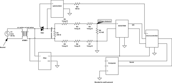
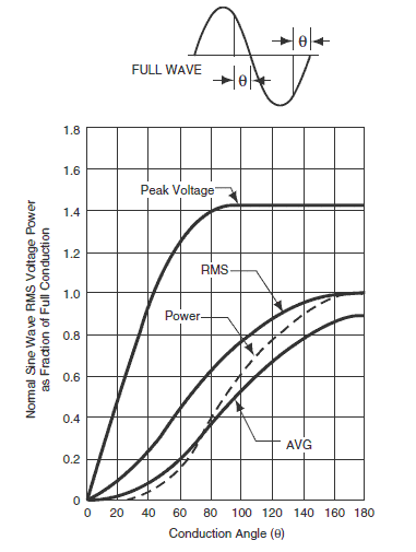
As I vary the duty cycle of my TRIAC (one second period,) the expected output voltage is input voltage * sqrt(duty_cycle). I am measuring that output voltage. I have an isolation transformer (a 1:1 style,), and a two pole variac (schematic below.)
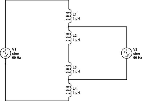
simulate this circuit – Schematic created using CircuitLab
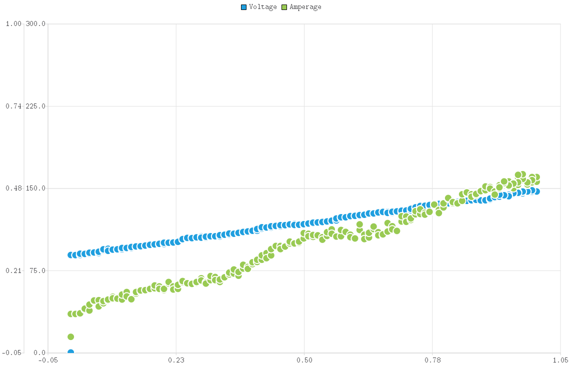
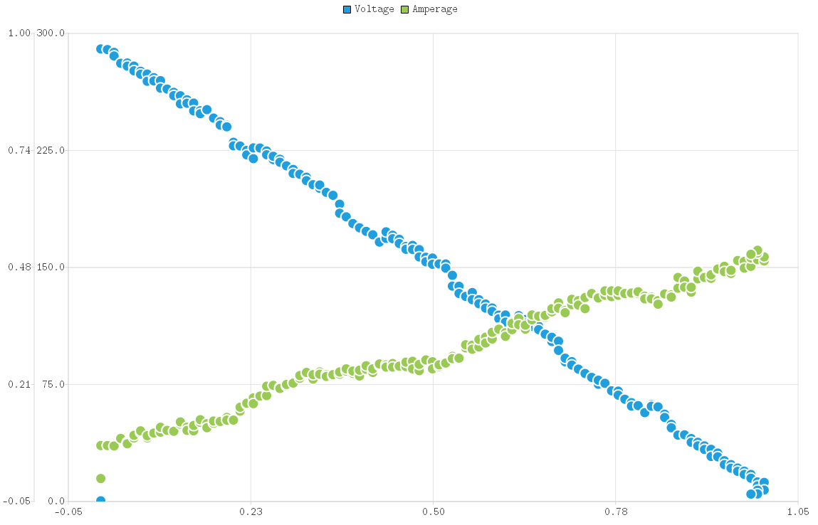
When I run the autotransformers with an output of 120V, everything looks as expected. When I run the isolation transformer, there is an offset for 0 output (like 80volts,) and the voltage at full on is much lower. The weird part is when connected without any transformer, my measured values are actually inverted (as if I am measuring the voltage across the TRIAC, but I am not.) Instead of voltage vs duty cycle looking like f(x) = 300x, it looks like f(x) = 300(1-x). I do know that the external circuitry which essentially connects earth ground to the DC ground plays a role. I am trying to simulate this effect in LTspice and have not been successful.
How can this be simulated in LTspice? My assumptions of a resistance between earth ground and digital ground so far only results in f(x) = x*c, where the constant c changes.
Here is a representative schematic
