0
\$\begingroup\$

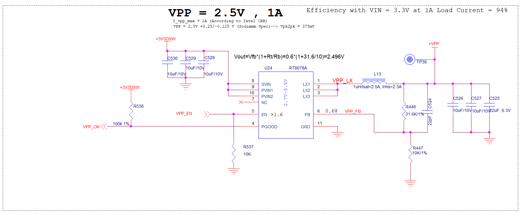
I intend to use RT8068A in the following design:

enter image description here

The requirements are: Vin = 3.3V, Vout= 2.5V, Iout_Max = 1A (+VPP is connected to DDR4 Memory SODIMM-260, 32GB, 2400MHz/2666MHz, 1.2V).

My question is, how do I know the maximum current that could go through the PVIN pins, in order to give it to the Layout Editor it's so she can define the width of PVIN Plane, based on the Manufacturer StackUp and trace details.

\$\endgroup\$
1
  • \$\begingroup\$ As always when it comes to power supplies etc, use the widest planes you can fit. :) \$\endgroup\$
    – Klas-Kenny
    Commented Dec 21, 2021 at 6:48

1 Answer 1

2
\$\begingroup\$

The maximum current that could go through the Vin pin is whatever the source impedance can source. If there is a failure within the freewheel path (ie FWD fails short ).

This is obviously a failure mode and while it is important to consider it's not really the answer you need.

The simplest method is conservation of energy:. Pin = Pout + loss. With Pout = 2.5V X 1A = 2.5W, assuming 95% efficiency implies an input power of 2.63W. With an input voltage of 3v3, the current would be 0.80A

Considering IPC-2152 and a 5C temprise and 0.5oz copper, you need ~0.7mm wide trace. However, this will eventually feed DDR4 and thus the PDN needs to be considered, along with stray inductance. A suitable plane and several vias connecting Vin to the power plane should suffice

NOTE you mention Bout should be 2.5V but it is also connected to DDR4, which had a rail need of 1v2, be sure the rail is set correctly

\$\endgroup\$

Your Answer

By clicking “Post Your Answer”, you agree to our terms of service and acknowledge you have read our privacy policy.

Not the answer you're looking for? Browse other questions tagged or ask your own question.