0
\$\begingroup\$

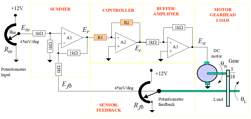
Derive the transfer function of:

a) The controller, in terms of R1 and R2;
b) The buffer/amplifier block.

What is the purpose of this last block?

I have done questions on finding transfer functions but I'm not familiar with finding it in terms of the resistors of an op-amp. Does anyone have any idea on how to work this out?

From what I know the purpose of a buffer block is that the buffer has an output that exactly mirrors the input and the input impedance of the op-amp buffer is very high, close to infinity. And the output impedance is very low, just a few ohms.

Here's what the diagram looks like:

enter image description here

\$\endgroup\$
4
  • \$\begingroup\$ Its a standard inverting amplifier. Just about any tutorial on opamps will get you going. \$\endgroup\$
    – Kartman
    Commented Dec 22, 2021 at 10:43
  • \$\begingroup\$ Probably a "power amplifier" for A3 ... for driving a motor ... unless it is a "micro" motor. \$\endgroup\$
    – Antonio51
    Commented Dec 22, 2021 at 12:02
  • \$\begingroup\$ You will notice from the schematic, that the amplifier drives the motor. So, the amplifier must be capable of supplying enough power to drive the motor. \$\endgroup\$
    – user16324
    Commented Dec 22, 2021 at 15:09
  • \$\begingroup\$ @JQ_ Qa and Qb are simply stages that can be studied independently and are obvious. So, apply the classic formula for these. If one want study the whole system, then you need also a "equivalent" schematic of the motor. this can help you enib.fr/~kerhoas/mcc.html . As there is a mechanical pot. feedback, it seems more a servo-motor. \$\endgroup\$
    – Antonio51
    Commented Dec 22, 2021 at 16:33

3 Answers 3

0
\$\begingroup\$

The last stage has a gain of

\$\frac{V_{out}}{V_{in}}=-\frac{R_1}{R_2}=Gain\$

which means it inverts the voltage from the last stage. If you didn't have the last stage what would the overall feedback be of the loop? Hint: the controller is also a inverting stage.

\$\endgroup\$
0
\$\begingroup\$

schematic

simulate this circuit – Schematic created using CircuitLab

A1 is the summ, A2 is the controller and A3 is the power amplifier. It is impossible to use A2 opamp as a complex controller unless you do use the negative opamp input as general input. Therefore you have to invert the output signal of A2 and do power amplification with A3.

\$\endgroup\$
1
  • \$\begingroup\$ thank you! Do u happen to have any idea on how to convert the whole diagram above to a block diagram too? \$\endgroup\$
    – QWERTY_
    Commented Dec 23, 2021 at 8:35
0
\$\begingroup\$

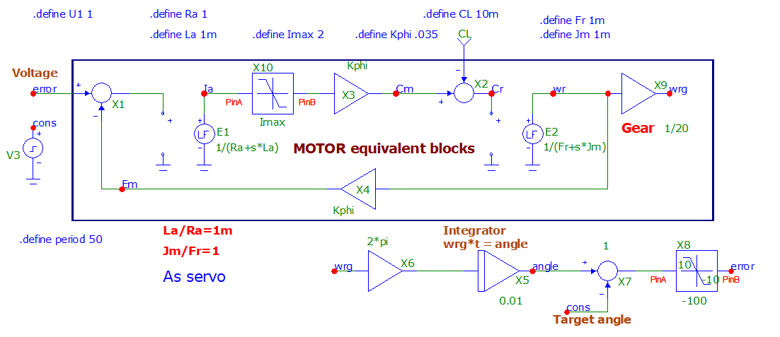
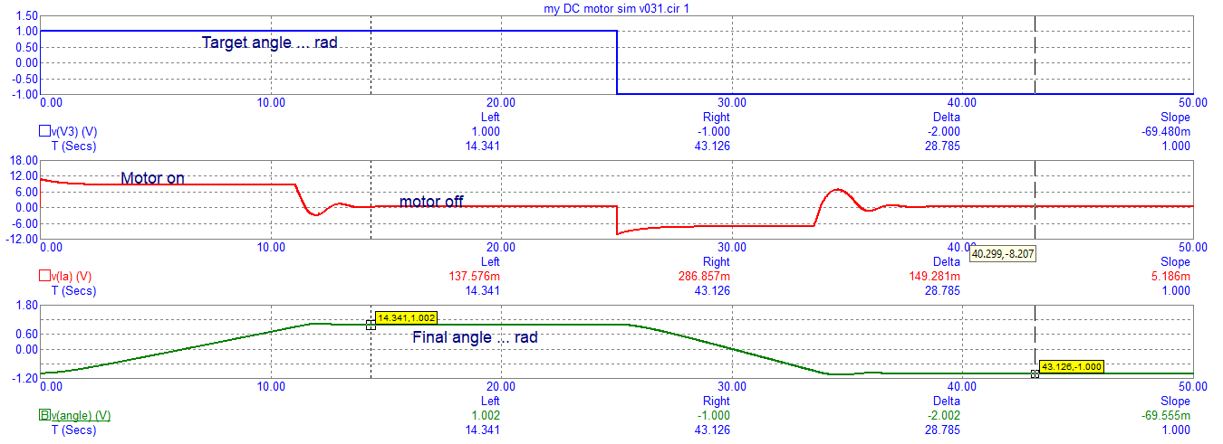
Example of an electric block diagram of picture. Simulated with free microcap v12.

enter image description here

enter image description here

\$\endgroup\$

Your Answer

By clicking “Post Your Answer”, you agree to our terms of service and acknowledge you have read our privacy policy.

Not the answer you're looking for? Browse other questions tagged or ask your own question.