-3
\$\begingroup\$

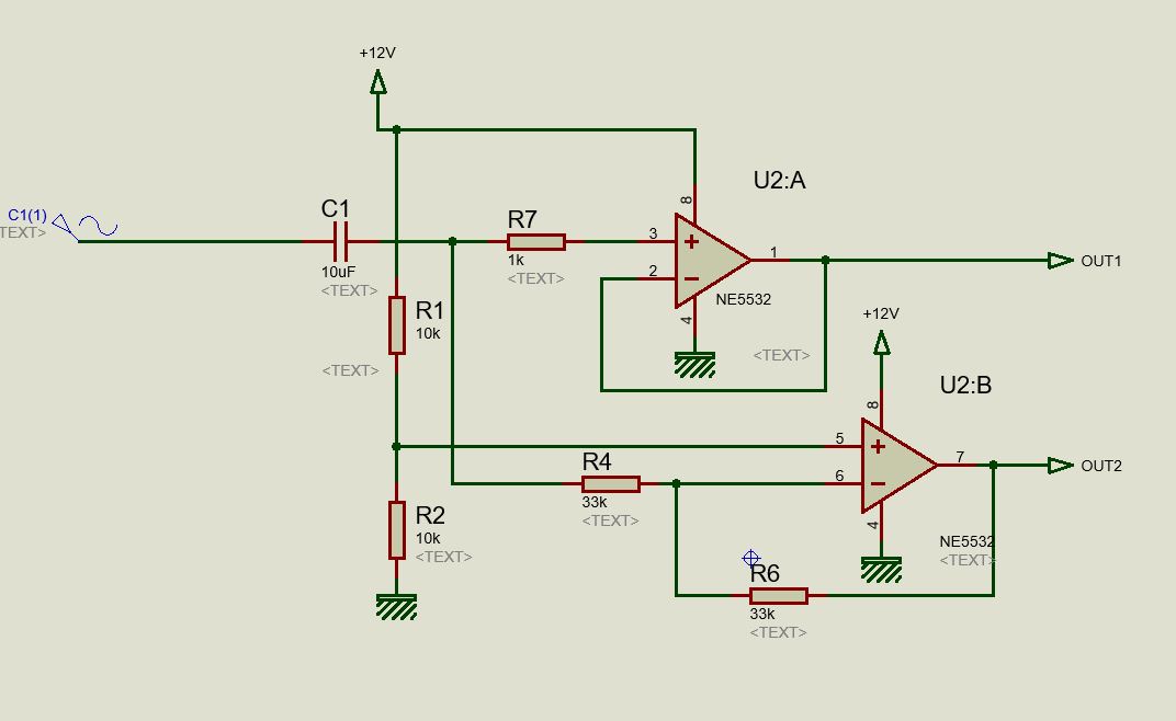
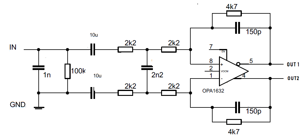
can I replace this fully differential Op-amp (OPA1632) with a generic op-amp based design ( Figure 2: Using NE5532). The Application area is audio signal handling.

  • Input: Differential input / single ended
  • Output: Differential output

Application: TAS5630 input drive original design

Original Design

Found One circuit from Internet ,but Not sure will it work or not

I found one circuit on the internet, but I am not sure if it will work.

\$\endgroup\$
9
  • 2
    \$\begingroup\$ hi. You'll notice this is not a free design house. "how to implement" is not a precise question we can answer other than doing your work for you! You're more than welcome to rephrase your question to explain exactly where you're stuck, and what the schematic you've added has to do with your problem. (It seems completely, fully, confusingly, unrelated). Voting to close as lacking detail for the time being - but happy to vote to reopen once you show your own effort and ask a precise question of your own. \$\endgroup\$ Commented Dec 27, 2021 at 13:40
  • \$\begingroup\$ More Details added \$\endgroup\$
    – Jestin
    Commented Dec 27, 2021 at 13:53
  • 2
    \$\begingroup\$ " found this" is not any meaningful clarification of your own thought. \$\endgroup\$ Commented Dec 27, 2021 at 14:05
  • \$\begingroup\$ The first stage of true differential amplifier could be used instead i.sstatic.net/JBQKW.png . To be adapted for unipolar supplies. \$\endgroup\$
    – Antonio51
    Commented Dec 27, 2021 at 14:45
  • \$\begingroup\$ @Antonio51 That diff input stage doesn't set the common mode output to a constant value \$\endgroup\$
    – Neil_UK
    Commented Dec 27, 2021 at 15:29

1 Answer 1

1
\$\begingroup\$

I found one circuit on the internet, but I am not sure if it will work.
At DC and low frequencies, the average voltage of the two outputs will be equal to the reference voltage created at the junction of R1/2, and they will be in anti-phase.

Due to the different noise gains of the inverting and non-inverting stages, there will be an increasing error in the anti-phase accuracy in both amplitude and phase as the frequency increases. That's probably going to be insignificant for your audio application. Implement the circuit in a simulator to check how big the error is if you are concerned.

\$\endgroup\$
2
  • \$\begingroup\$ Thanks Neil_UK , is there any method to check error ? giving a 20khz at input and check the phase and amplitude at output sides ? something like this \$\endgroup\$
    – Jestin
    Commented Dec 27, 2021 at 14:35
  • \$\begingroup\$ There's a difference between knowing what the error from this circuit is, and knowing what the largest error is that the circuit you're driving can tolerate. An error is going to cost you a small hit in maximum output balanced signal, which is probably irrelevant. \$\endgroup\$
    – Neil_UK
    Commented Dec 27, 2021 at 15:31

Not the answer you're looking for? Browse other questions tagged or ask your own question.