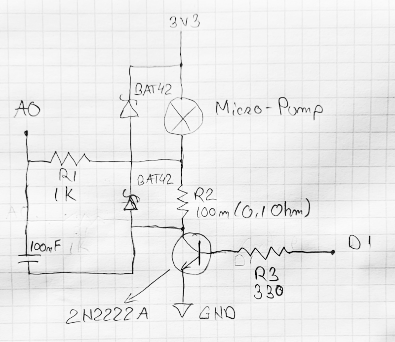
I am doing a personal project with a Wemos D1 mini and one thing that was of interest to me was to detect a servo-motor stall. I was very glad to find an useful answer to this question: How do I detect servo stall with an Arduino?
I re-created the schematic provided by @KryanF (which seemed to be very useful) and gave it a shot, but using a submersible water pump (since my servo is still on the way). According to the pump data, it should take 0.12 A when powered at 3.3 V or 0.18 A when powered at 5 V.
I powered my micro-pump with 3.3 V and use a digital multimeter to verify the running current and it shows, indeed 0.12 A. When reading the ADC pin, I get values around 120 (they are varying between 100 and 140 with some peaks of 160.)
Now, let's start from this statement (from the above question):
Let's say for a value of 25 read on the ADC, 25 units * 4.88 mV/unit is 122 mV on the ADC input in the real world. The required current through the sense resistor to get 122 mV across it follows Ohm's law. V = IR, so 0.122 V = I * 0.1, which is 1.22 A.
In my case, the value per unit should be 3300/1024=3.22 mV/unit. So, a read from ADC of 120 translates in 386 mV. I also used a 0.1 Ω resistor, but when measured it show 0.3 Ω, so I'll be using 0.3 as R value.
My calculations shows like this: 0.386 V = I * 0.3, therefore I=1.28 A. Wow, this is A LOT for that micro-pump.
I realized that I can get the real value if I divide that by 10: 1.28 / 10 = 0.128 A, which is a much closer value to the reality. Verified this also when powering the pump with 5 V.
Well, I am not an electronics expert, just a hobby enthusiast with software experience who wants to do some home automation project. Regarding all the electronics, I just read the web.
This is the schematic I made:
Since I cannot power my micro-pump directly from a digital pin (since it outputs only 12 mA), I am using a transistor (2N2222A) connected to 3V3 and to the control pin (D1.)
I did some more measurements with the multimeter and, apparently, the A0 analog pin actually reads the correct value (no need to divide or anything else). The problem that I have is actually multiple problems:
- When reading A0 pin with no load on the micro-pump (D1 pin is LOW) I get 1024 (the same way as the A0 would be connected to a 3V3 pin). Is the current directly flowing through the micro-pump when it is idling?
- When the micro-pump is working, with D1 control pin on full load (with digitalWrite(HIGH),) I get on the A0 about 300 mV (the same, more or less as I get with the multimeter.) With Ohm's law this means about 3 A, but in reality (measured with multimeter) I have 0.8 A.
- When I try to power the micro-pump with a lower voltage, by controlling the D1 pin with analogWrite, for example an 80% duty-cycle with analogWrite(205) I get on voltage of about 1.2 V on A0 (and also by multimeter.)
If I apply the Ohm's law on that circuit I get, in theory, 12 A! That is crazy, indeed, because the current measured with a multimeter when the micro-pump is running on 80% duty-cycle is actually about 0.4 A.
There must be something that I am missing here, since this circuit cannot be used to actually measure the current drawn by a DC motor.
BTW: I also tried to connect the end of the second BAT42 to the transistor emitter instead of the collector, but I get the same results.

