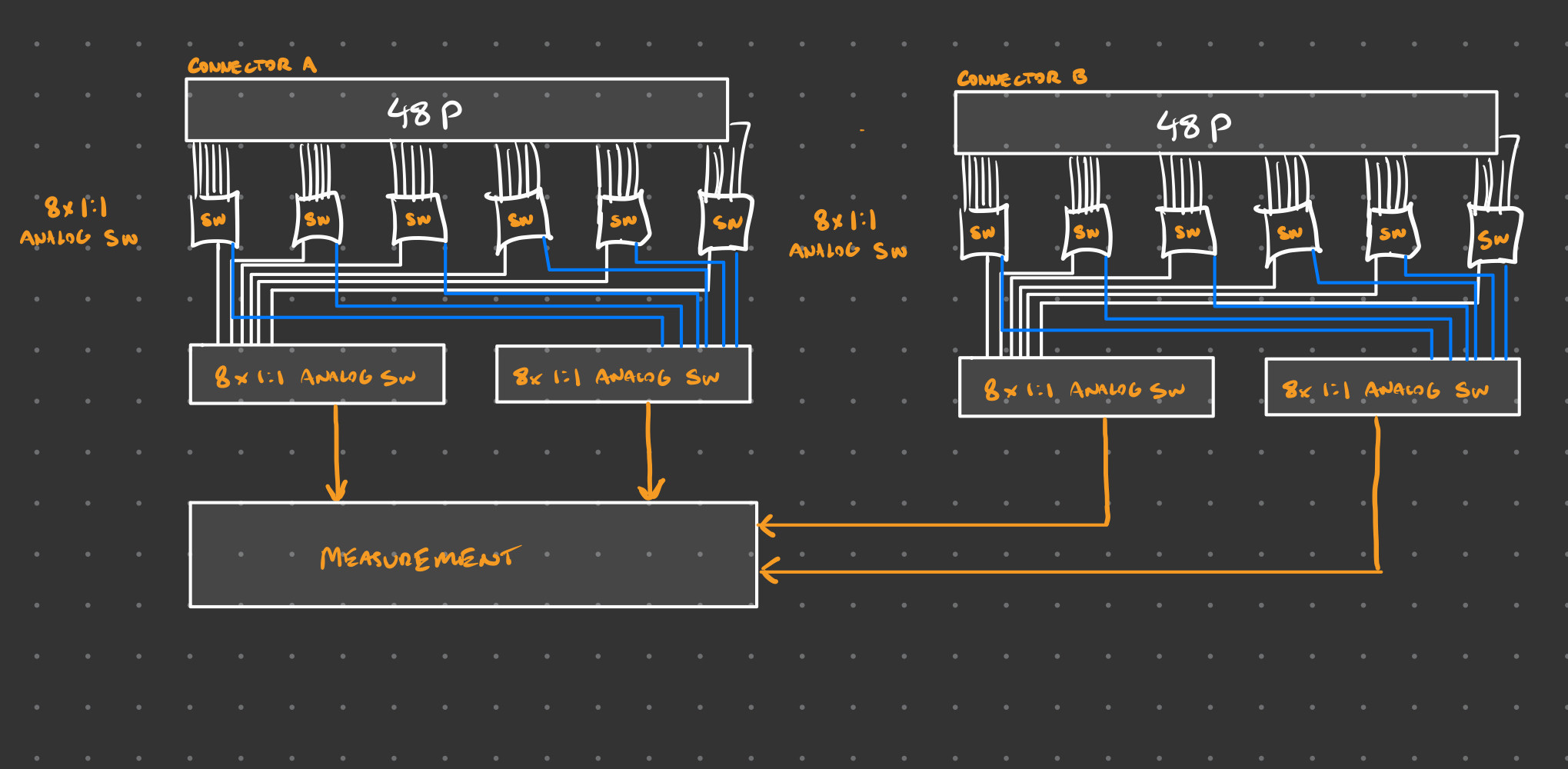
Reaching out as I am in the initial stages (read: crude block diagram) of circuit design for a project aiming to automate resistance checks between various connectors. We'll call these connections A and B. Each connector has 48 lines. These connectors interface with a PCB. This PCB mostly consists of an adapter from A to B but also contains passive components which I'd like to also test resistance (these have a specification defined below).
Testing for short circuits between each pin of B is required due to the quality control nature of this device.
As of right now, I've gone with (6) 8x 1:1 analog switches for each connector and (2) 8x 1:1 analog switches behind each for measurement bus selection (dependent on if the measurement is from Connector A->B, A->A, B->B). This seems like a bit much to me, with the number of analog switches reaching sixteen.
Resistance measurements must be taken from various lines belonging to A and B. Of note, the connections between A and B are not straight through. The measurements taken will require to not only go from each connector but between lines on each connector themselves (shown below):
A --> B
A --> A
B --> B
Additionally, the expected resistance measurements fall within a range of acceptable standards dependent on which pair is under test:
less than 1.0 ohm
between 300-360 ohms
above 150k ohms
The outputs from the (2) 8x 1:1 analog switches will then be presented to constant current ohmmeter circuitry which in turn is fed to an ADC for usage by the main MCU.
For this application, what is the best topology for the analog switches? Or is there another solution I am overlooking?
I hope I've provided enough information. In the fear of none of the above making sense, I've included the crude block diagram of what I have thus far. Any suggestions for optimization would be much appreciated, I've found myself a bit blocked up.
Thanks!

