1
\$\begingroup\$

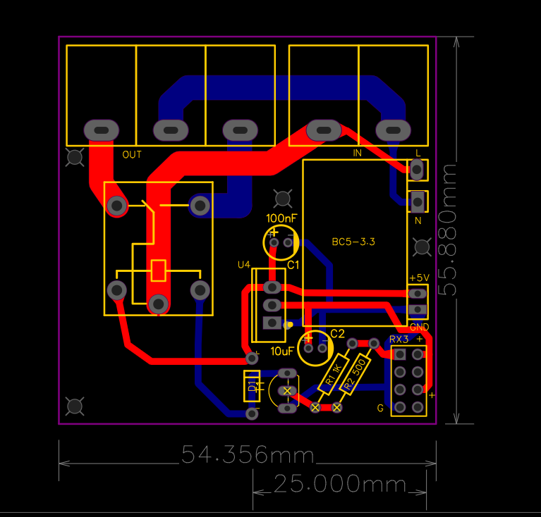
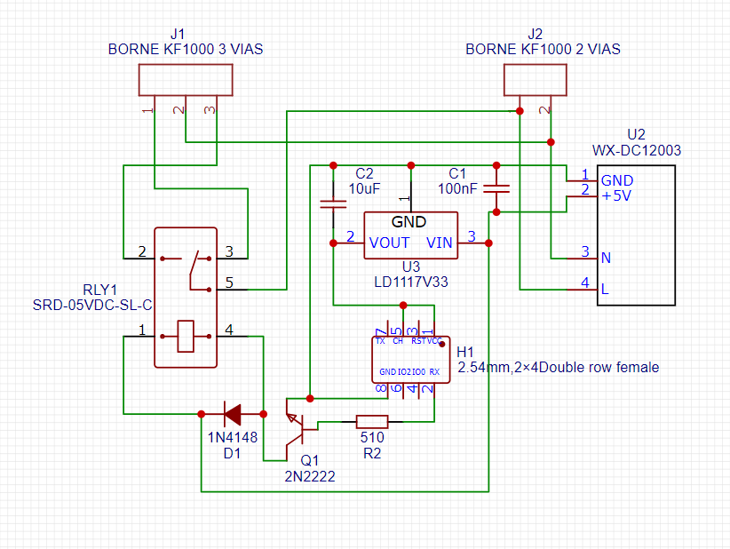
I have 5V relay circuit to control 3 220V fluorescent lamps using ESP-01. What I found sometimes the relay get stuck on "ON position" randomly. I have multiple of these around my house. I'm just wondering if this is some circuit design issue or poor quality components or anything else. please share your thoughts.

BOM List:

  • 100nF Capacitor (C1)
  • 10uF Capacitor (C2)
  • 1N4148 (D1)
  • 2.54mm,2×4Double row female (H1)
  • KF1000-2P (J1) (220V Power Source)
  • KF1000-3P (J2)
  • 2N2222 (Q1)
  • 510 Ohm Resistor (R2)
  • SRD-05VDC-SL-C (RLY1)
  • WX-DC12003 (U2) (220V AC to 5V DC)
  • LD1117V33 (U3)

enter image description here enter image description here

\$\endgroup\$
3
  • \$\begingroup\$ So is the ESP really controlling the relay on so the issue is thay ESP is stuck and keeps relay on, or do the relay contacts just weld together? \$\endgroup\$
    – Justme
    Commented Jan 31, 2022 at 15:38
  • \$\begingroup\$ Not the first to have this problem. This looks like an almost identical question, same relays switching fluorescent lighting. forum.arduino.cc/t/relay-switch-stuck-in-one-state/421401 \$\endgroup\$
    – GodJihyo
    Commented Jan 31, 2022 at 15:48
  • \$\begingroup\$ What is the ballast rating of the relay? (or tungsten rating if the fluorescent ballasts are electronic / no-buzz / no-flicker). \$\endgroup\$ Commented Feb 1, 2022 at 3:12

4 Answers 4

2
\$\begingroup\$

Your relay is not capable of reliably handing the surge due to the electronic ballast. This tends to be more of a problem at 220VAC compared to 120VAC. It's a design issue- the relay is reliable when used within ratings.

A relay such as this one (the TV-8 version) has a much better chance of working reliably, however the cost, power requirements and size are all higher.

Even a TV-5 rated relay should help- some are available in a compatible package, however the power requirement is typically more like 560mW than 360mW and the contact material will be different (usually AgSnO rather than AgCdO).

\$\endgroup\$
1
\$\begingroup\$

Flourescent lamps tend to have a large inrush current when powered. This can easily cause the contact inside a relay to "weld" stuck, when you power it on.

The easiest solution to this is probably to change the relay to a more powerful one, or to an SSR (Solid-State-Relay).

\$\endgroup\$
1
  • \$\begingroup\$ Old fluorescents have enormous inductive kick when interrupted at the wrong instant in the AC cycle. New electronic-ballast fluorescents have inrush (like incandescents) to charge the capacitors in their switching power supplies. \$\endgroup\$ Commented Feb 1, 2022 at 3:16
1
\$\begingroup\$

Tungsten ratings are applicable to modern fluorescents with electronic ballasts, these don't hum or flicker, and start fine when cold. I love 'em. Ballast ratings are applicable to older fluorescents with big inductive transformers inside - easy to know if you have one; they hum!

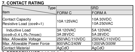
This relay does have RU Recognition and a spec sheet.
enter image description here

Form C version of these relays isn't permitted over 125VAC at all.
I'll be gracious and assume you have Form A.

No specification of a tungsten rating.

No specification of a ballast rating.

There's an inductive rating, but maximum 120VAC when used that way.

These are simply not fit for purpose.

ObDisclaimer: Installing things like this into houses is foolhardy, and a Code violation. Meaning insurance won't pay and you'll be sued for the burn-down or accident. Do not mess around with AC mains! Unless you are learning to learn the full chapter-and-verse of Codes and standards in your jurisdiction, and pull permits from local authorities where called for. The DIY stack specializes in this. Most places require approved equipment (not mail-order hobby stuff) - UL Listing, BSI kite mark, etc. To switch or dim AC mains, feel free to use the many approved COTS plug-in controls that use WiFi or other protocols.

\$\endgroup\$
1
\$\begingroup\$

An NTC inrush current limiter, in series with the fluorescent lamp, could solve the problem.

Cold resistance of the NTC thermistor would limit the inrush current during initial turn-on.

With the thermistor heating up following continuous flow of current, its resistance would reduce to a very low level that would allow the operating current to flow for normal operation.

\$\endgroup\$

Your Answer

By clicking “Post Your Answer”, you agree to our terms of service and acknowledge you have read our privacy policy.

Not the answer you're looking for? Browse other questions tagged or ask your own question.