1
\$\begingroup\$

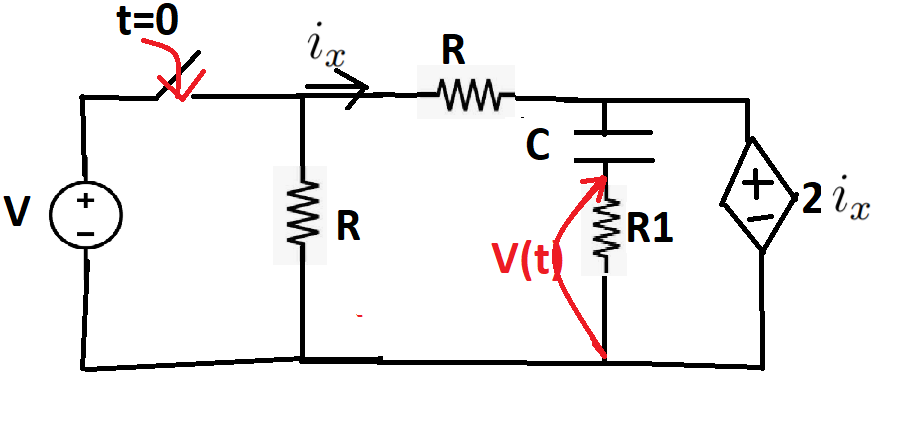
I found this problem and it confused me a bit and I was hoping someone can clear me on this.

Basically as I said we have to find the voltage across the resistor when the switch turns.

This is a picture of the exercise (sorry for using paint) enter image description here

The thing that confuses me is that the voltage source is initially separated from the rest of the circuit and I know that we have a dependent voltage source but since that depends on the ix current and we dont have a "full" capacitor that can serve as a voltage source can we assume that the voltage across the capacitor and the resistance in series with the capacitor initially is 0?

So all in all what I'm asking is :what is the voltage v(t) across the resistor R1 in series with the capacitor for t<0

\$\endgroup\$
20
  • \$\begingroup\$ I find your circuit confusing for initially ( when the switch is OPEN, no current ) there is this current generator that deliver 2ix current , yet further up there is an indication that the current is ix. Which makes no sense because the series C R1 have current to zero, because no current can circulate through a capacitor in a DC circuit. So initially , is there a 2ix current in the loop or is there a ix current in the loop ? \$\endgroup\$ Commented Feb 21, 2022 at 0:53
  • \$\begingroup\$ @FredCailloux im not sure if i understood your question but the ix i have there is just an indication where the dependent voltage source takes the ix from. And that is why im confused as well. The problem said "Find v(t) across the resistor". As i said in the question above if there is no initial source to "fill up " the capacitor can we assume that all the values are 0 in the begining? \$\endgroup\$
    – Ani Lici
    Commented Feb 21, 2022 at 1:58
  • \$\begingroup\$ can we assume that the voltage across the capacitor and the resistance initially is 0? - be precise here. \$\endgroup\$
    – Andy aka
    Commented Feb 21, 2022 at 10:27
  • \$\begingroup\$ @Andyaka at t<0 when the switch is open. Since the capacitor is not charged in any way i thought that even though there is a dependent voltage source we dont have an actual voltage source for it to work. I dont know if i was clear but basically im asking. What is the voltage across the capacitor and resistance @t<0 \$\endgroup\$
    – Ani Lici
    Commented Feb 21, 2022 at 10:48
  • \$\begingroup\$ @Andyaka Since the dependent voltage depends on the current ix but there is no voltage source to drive that ix i thought or assume that the current ix is 0. Therefore there is nothing running in the circuit and therefore the voltage across the capacitor and resistor is 0 \$\endgroup\$
    – Ani Lici
    Commented Feb 21, 2022 at 10:50

2 Answers 2

1
\$\begingroup\$

Let us initially address your inquiry: The initial currents and voltages across all components are equal to zero for \$t<0\$, as \$2\text{I}_x\$ is contingent upon \$\text{I}_x\$, and it becomes evident that \$\text{I}_x=0\$ for \$t<0\$.


Well, we are trying to analyze the following circuit:
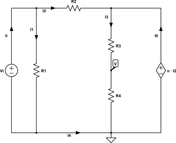
schematic

simulate this circuit – Schematic created using CircuitLab

When we use and apply KCL, we can write the following set of equations:

$$ \begin{cases} \begin{alignat*}{1} \text{I}_\text{i}&=\text{I}_1+\text{I}_2\\ \\ \text{I}_3&=\text{I}_0+\text{I}_2\\ \\ \text{I}_1&=\text{I}_\text{i}+\text{I}_4\\ \\ \text{I}_0&=\text{I}_3+\text{I}_4 \end{alignat*} \end{cases}\tag1 $$

When we use and apply Ohm's law, we can write the following set of equations:

$$ \begin{cases} \begin{alignat*}{1} \text{I}_1&=\frac{\displaystyle\text{V}_\text{i}-0}{\displaystyle\text{R}_1}\\ \\ \text{I}_2&=\frac{\displaystyle\text{V}_\text{i}-\text{n}\cdot\text{I}_2}{\displaystyle\text{R}_2}\\ \\ \text{I}_3&=\frac{\displaystyle\text{n}\cdot\text{I}_2-\text{V}}{\displaystyle\text{R}_3}\\ \\ \text{I}_3&=\frac{\displaystyle\text{V}-0}{\displaystyle\text{R}_4} \end{alignat*} \end{cases}\tag3 $$

Substitute \$(2)\$ into \$(1)\$, in order to get:

$$ \begin{cases} \begin{alignat*}{1} \text{I}_\text{i}&=\frac{\displaystyle\text{V}_\text{i}-0}{\displaystyle\text{R}_1}+\frac{\displaystyle\text{V}_\text{i}-\text{n}\cdot\text{I}_2}{\displaystyle\text{R}_2}\\ \\ \frac{\displaystyle\text{n}\cdot\frac{\displaystyle\text{V}_\text{i}-\text{n}\cdot\text{I}_2}{\displaystyle\text{R}_2}-\text{V}}{\displaystyle\text{R}_3}&=\text{I}_0+\frac{\displaystyle\text{V}_\text{i}-\text{n}\cdot\text{I}_2}{\displaystyle\text{R}_2}\\ \\ \frac{\displaystyle\text{V}_\text{i}-0}{\displaystyle\text{R}_1}&=\text{I}_\text{i}+\text{I}_4\\ \\ \text{I}_0&=\frac{\displaystyle\text{n}\cdot\frac{\displaystyle\text{V}_\text{i}-\text{n}\cdot\text{I}_2}{\displaystyle\text{R}_2}-\text{V}}{\displaystyle\text{R}_3}+\text{I}_4\\ \\ \frac{\displaystyle\text{V}-0}{\displaystyle\text{R}_4}&=\text{I}_0+\frac{\displaystyle\text{V}_\text{i}-\text{n}\cdot\text{I}_2}{\displaystyle\text{R}_2}\\ \\ \text{I}_0&=\frac{\displaystyle\text{V}-0}{\displaystyle\text{R}_4}+\text{I}_4 \end{alignat*} \end{cases}\tag3 $$

Now, let's solve for \$\text{V}\$:

$$\text{V}=\frac{\displaystyle\text{V}_\text{i}\text{n}\text{R}_4}{\displaystyle\left(\text{n}+\text{R}_2\right)\left(\text{R}_3+\text{R}_4\right)}\tag4$$

Now, applying this to your circuit we need to use (from now on I use the lower case letters for the function in the 'complex' s-domain where I used Laplace transform):

  • $$\text{R}_3=\frac{\displaystyle1}{\displaystyle\text{sC}}\tag5$$
  • The input voltage is a stable DC voltage equal to \$\hat{\text{u}}\$, so: $$\text{v}_\text{i}\left(\text{s}\right)=\frac{\displaystyle\hat{\text{u}}}{\displaystyle\text{s}}\tag6$$

So, we get:

$$\text{v}\left(\text{s}\right)=\frac{\displaystyle\frac{\displaystyle\hat{\text{u}}}{\displaystyle\text{s}}\cdot\text{n}\text{R}_4}{\displaystyle\left(\text{n}+\text{R}_2\right)\left(\frac{\displaystyle1}{\displaystyle\text{sC}}+\text{R}_4\right)}\tag7$$

Taking the inverse Laplace transform, leads to:

$$\text{V}\left(t\right)=\frac{\displaystyle\text{n}\hat{\text{u}}}{\displaystyle\text{n}+\text{R}_2}\cdot\exp\left(-\frac{\displaystyle t}{\displaystyle\text{CR}_4}\right)\tag8$$
\$\endgroup\$
0
\$\begingroup\$

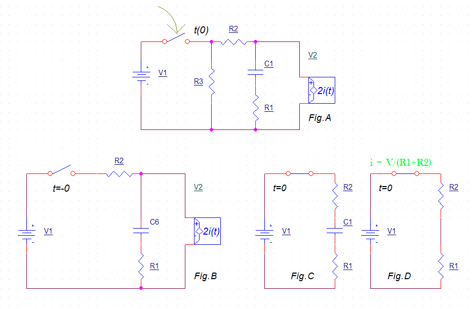
Here is my proposed solutionenter image description here

Lets pose that R1 = R2 = R3. Pose that R3 current is not part of i (as per your circuit). For sake of simplification we can then take R3 out of the circuit [fig.C] because iR3 is determined by iR3= V1/R3, and this will not change since V1 is theoretically zero ohm impedance. Pose that, with the switch OPEN, all voltages and currents are zero, except for V1. Also, we know that C1 act as a short circuit when v/t is infinite, which is the case when the switch is momentarily closed.

When the switch CLOSE the voltage on R3 is V, but we don’t care since iR3 is of no interest for our analysis. The voltage between R2\C1\R1 = V (assuming that V2 is a current source with infinite impedance). Since C1 is a short, then i = V/(R1+R2) [fig.D]. Now that i is calculated, we know that 2i = 2 x i. If C1 is short we have to split the current 2i between R1 and R2. Since i2 is double of i then V(R1) will very quickly attain a value equal to V1 since R1=R2 and i2 (which is double the value of i) will induce into R1 the same voltage originally equal to V1.

For sake of explanation let’s utilize some values to better understand what’s happening. Say that V1 = 10 volts and R1=R2=5 ohms. 10V/(5Ω+5Ω)=1A. 2i=2A. 2A on 5Ω = 10Volts. If we now have 10V on R1 and 10V as V1 then R2 will see a voltage of zero volt, hence no current, i now equal zero. But by that time the capacitor will have attain 10 volts and i will now remain at zero since the capacitor is now charged to 10V. No more current will flow in R2 and R1. Since i is now zero then 2i is also zero. As for R3, its current will be 10V/5Ω = 2A.

In essence, that circuit is an RC circuit which the time constant equal to (R1+R2)xC1 except that the value of the time constant must be divided by some factor since the total current imposed on R1C1 is 3 time more than if there was no V2 source. So, instead of considering the C1(R1+R2) time constant one should consider that time constant equal to 0.33C1*(3R1+R2) because the V2 source modify the R1C1 impedance by multiplying it by a factor of 3 (which is determined by 1i+2i=3i.

Since the original question is: What is the voltage on R1 when t=0 (right at the exact moment when the switch is closed)? The answer is V(R1) = half of V1. Because the instantaneous voltage seen by the circuit is V. Since R1=R2 and C1 is a short circuit, then we will see on R1 a value of 0.5V1 because R1\R2 is a simple voltage divider. The mind trick here is when you start to consider the source V2. Here, V2 will only lower the time constant by a factor of 3, but since we are not interested about what’s happening after the switch is closed but rather immediately when the switch is closed, we do not have to consider V2. So, we are left with the simplified circuit such as in fig.D, only at t(0).

\$\endgroup\$

Your Answer

By clicking “Post Your Answer”, you agree to our terms of service and acknowledge you have read our privacy policy.

Not the answer you're looking for? Browse other questions tagged or ask your own question.