0
\$\begingroup\$

So I am designing a circuit in MATLAB simulink which is basically a rectifier followed by a DC/DC converter.

Both simulations are working perfectly individually. However, when I attach the DC/DC converter to the rectifier the simulation becomes excruciatingly slow. It's impossible for me to analyze it.

Hence I am considering if it would be appropriate to model the DC/DC converter in a simpler way by using the current and voltage data points available from simulation of the individual DC/DC converter. Right now I am considering a variable resistor model, by dividing the input voltage by input current of the DC/DC converter at each time instant.

Will this be mathematically and electrically accurate or am I missing something?

\$\endgroup\$
8
  • \$\begingroup\$ Have you fitted a smoothing capacitor on the output of the rectifier? \$\endgroup\$
    – Andy aka
    Commented Mar 1, 2022 at 16:30
  • \$\begingroup\$ @Andy aka yes there is a capacitor at the output of rectifier. \$\endgroup\$ Commented Mar 1, 2022 at 16:30
  • 1
    \$\begingroup\$ I think you need to show your circuit. \$\endgroup\$
    – Andy aka
    Commented Mar 1, 2022 at 16:34
  • 1
    \$\begingroup\$ You'll probably need to help the solver, it sounds like convergence problems. Without seeing any schematic, it's impossible to say what/who/where, but you could try to add some small capacitances across the rectifier diodes (series RC snubbers), or across the nodes that have the sharpest transitions. \$\endgroup\$ Commented Mar 1, 2022 at 17:07
  • 1
    \$\begingroup\$ The easiest way is to model the dc-dc converter with a constant power load which is a current source whose value is \$i(t)=\frac{P_{out}}{v_{in}(t)}\$. This mimics a converter featuring a negative incremental resistance and an infinite input voltage rejection. \$v_{in}(t)\$ represents the voltage across the current source. \$\endgroup\$ Commented Mar 1, 2022 at 18:55

2 Answers 2

4
\$\begingroup\$

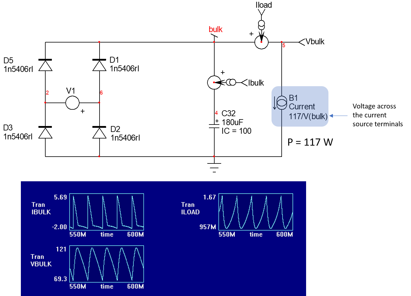
The easiest way to model a regulating dc-dc converter is to use a constant power source. It can be modeled as a voltage-controlled current source. The instantaneous current depends on the power absorbed by the dc-dc and the voltage across the current source terminals: \$i(t)=\frac{P_{out}}{v_{in}(t)}\$ in which \$v_{in}(t)\$ represents the instantaneous voltage controlling the current and \$P_{out}\$ the power delivered by the converter. This offers the advantage of modeling a negative incremental resistance and provides a good way to check the interaction with a front-end EMI filter.

The below drawing shows a typical application in a front-end rectifier and lets you assess the ripple amplitude when the bulk capacitor is loaded by the constant-power source:

enter image description here

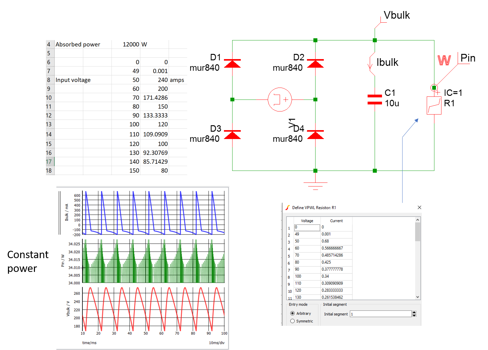
You can also use a voltage-dependent resistor called a PWL resistance in SIMPLIS. Using an Excel sheet, you compute the resistance value based on the applied voltage and considering a constant power:

enter image description here

The divide-by-zero case when the bulk capacitor is discharged should often be considered by adding a .IC defining an initial charge.

\$\endgroup\$
3
  • \$\begingroup\$ could you suggest a resource I could read about this from in detail? The modelling as a constant power source looks interesting. \$\endgroup\$ Commented Mar 5, 2022 at 17:40
  • \$\begingroup\$ I am not sure there are many details in the literature. I remember discussing it in my APEC 2017 seminar you can download from my site but I use it to test EMI stability which is also an important topic. \$\endgroup\$ Commented Mar 5, 2022 at 17:47
  • \$\begingroup\$ My DC/DC converter also needs to charge a battery with CC-CV control...I don't think it would be possible using this model. I made a detailed post about my exact issue today: electronics.stackexchange.com/questions/610916/… . Could you take a look? \$\endgroup\$ Commented Mar 5, 2022 at 17:51
0
\$\begingroup\$

It depends on what you are trying to model. But a switch-mode DC/DC converter doesn't really look much like a variable resistor.

If it's stepping down the voltage, then it can deliver more current on the output than is drawn from the input. No resistor network can do that.

\$\endgroup\$

Your Answer

By clicking “Post Your Answer”, you agree to our terms of service and acknowledge you have read our privacy policy.

Not the answer you're looking for? Browse other questions tagged or ask your own question.