0
\$\begingroup\$

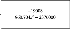
So I am dealing with a project that revolves around magnetically levitating an object below an electromagnet. I created a transfer function of it after making a mathematical model of it, and got this as my result: enter image description here

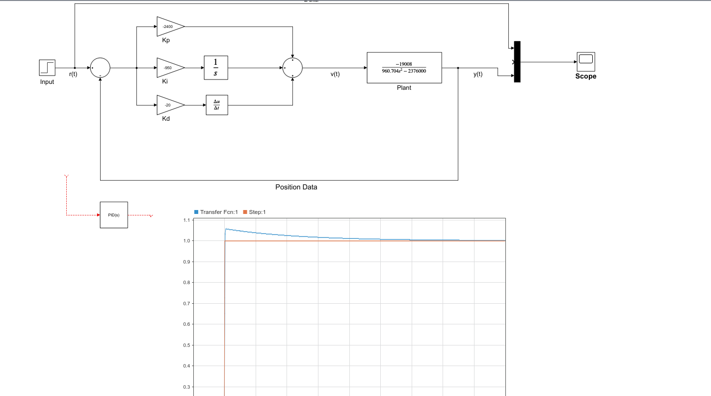
Now when I put this on MATLAB's Simulink in order to use its PID functions to tune it, I got exceptionally large values in which I then inserted into the gains as you can see in the figure below. When running these gains, I got a stable result. enter image description here

However, when I put this code in my Arduino's magnetic levitation code, specifically the PID parameters, it just became a vibration machine that would just vibrate my neodymium magnet to be levitated and that was it. No stability, if i let go then it would stick up.

I'm genuinely confused as to why I have received such different outputs when testing it in real life.

For more information, I got this system by doing a mechanical calculation(newton's second order equation of motion) of the forces of my electromagnet and the neodymium magnet's weight. My electromagnet has a nominal resistance of 5Ohms and Inductance 47mH. I am using a 12V 1A power supply. Schematics of this system are based off of this tutorial: https://www.hackster.io/jsirgado/magnet-levitation-with-arduino-eeeee4

\$\endgroup\$
8
  • \$\begingroup\$ neodymium magnet's weight. ... what about the force of the magnet's attraction to the electromagnet core? \$\endgroup\$
    – jsotola
    Commented Mar 31, 2022 at 17:48
  • \$\begingroup\$ It's weak, when the electromagnet is turned off, the neodymium magnet does not fly up to the electromagnet unless it gets turned on. \$\endgroup\$
    – Thanos
    Commented Mar 31, 2022 at 18:04
  • \$\begingroup\$ maybe the hall-effect sensor is not the linear type \$\endgroup\$
    – jsotola
    Commented Mar 31, 2022 at 18:07
  • \$\begingroup\$ Yeah it's a ratiometric one fortunately enough, can detect/output a range of values depending on the distance of the magnetic field \$\endgroup\$
    – Thanos
    Commented Mar 31, 2022 at 20:12
  • \$\begingroup\$ In addition to the mass of the magnet the strength and shape of it will also determine some of the control parameters. Note that even in the video the user needs to make an adjustment when trying to balance the cylindrical shaped magnet. \$\endgroup\$
    – Nedd
    Commented Mar 31, 2022 at 21:05

1 Answer 1

1
\$\begingroup\$

I believe your using the wrong equations for your transfer function. The equations that you are referencing to in the above article are for levitating a soft magnetic material (such as steel). If you are using a hard magnetic material (such as a permanent magnet) the equations are going to be different. The reasoning is that the mechanism that generates force is different. The soft magnetic material's force is due to the change in inductance vs change in position. Whereas the permanent magnets flux couples with the coil and the force mechanism is the change in magnetic flux vs the change in position.

In addition, a permanent magnet has the same permeability as air, so the inductance that the coil sees does not change with respect to the position of the magnet. Steel has a permeability around 2000 times that of air. Hence the inductance changes when the object gets closer or further from the coil.

The amount of flux that couples with the coil is going to change with respect to the position of the coil you are using. I would highly recommend modeling your system in FEMM and solving for the flux linkage at several magnet positions.

I will solve out for you so you can see the difference


First perform a power balance between mechanical power and electrical power. \begin{equation} P_m=\frac{Fx}{t}\\ P_e=vi\\ P_m=P_e=\frac{Fx}{t}=vi \end{equation} Next apply faradays law.

\begin{equation} v=\frac{d\lambda}{dt}\\ \end{equation}


For a soft magnetic object (steel) total magnetic flux \$\lambda\$ is a function of the inductance. The inductance is a function of the distance from the core. \begin{equation} \lambda = L(x)i \end{equation}

Now put it all together. I believe the chain rule is used here. \begin{equation} P_m=P_e=\frac{Fx}{t}=\frac{d\lambda}{dt}\\ \end{equation} Break down the derivative into partials. \begin{equation} \frac{Fx}{t}=\frac{i^2}{2}\frac{d(L(x))}{dx}\frac{dx}{dt} \end{equation} Finally canceling out the velocity term \$\frac{x}{t}\$ gives you the following relationship. \begin{equation} F=\frac{i^2}{2}\frac{d(L(x))}{dx} \end{equation}

Now look at the units to make sure they work out to be in Newtons \begin{equation} kg*m*s^2=(A^2)(kg*m^2*s^{−2}*A^{−2})(m^{-1}) \end{equation}## Heading ##


For a hard magnet material the total magnetic flux \$\lambda\$ is a function of the magnetic flux that couples with the coil. The inductance does not change with position \$L(x) = 0\$ so we can leave it out, as it contributes zero torque. \$\lambda_m\$ is the B field normal to the coil times the area of the coil (it comes from gauss law)

\begin{equation} \lambda = \lambda_m(x) + L(x)i\\ \lambda = \lambda_m(x) = B*A \end{equation}

Now put it all together \begin{equation} P_m=P_e=\frac{Fx}{t}=i\frac{d\lambda_m}{dt} \end{equation} Break down the derivative into partials. \begin{equation} \frac{Fx}{t}=i\frac{d(\lambda_m(x))}{dx}\frac{dx}{dt} \end{equation} Finally canceling out the velocity term \$\frac{x}{t}\$ gives you the following relationship. \begin{equation} F=i\frac{d(\lambda_m(x))}{dx} \end{equation}

Now look at the units to make sure they work out to be in Newtons \begin{equation} kg*m*s^2=(A)(kg*m^2*s^{−2}*A^{−1})(m^{-1}) \end{equation}


In conclusion in order to model \$\frac{d(\lambda_m(x))}{dx}\$ you likely need to use finite element analysis. I would recommend you make a simple model using FEMM. But the biggest difference is that you will see that the current is squared in one equation and not in the other equation. This kind of assumption would make a huge difference in your model.
\$\endgroup\$
4
  • \$\begingroup\$ Wait for real?? I thought they would be applicable for neodymium magnets, wow. \$\endgroup\$
    – Thanos
    Commented Apr 1, 2022 at 11:02
  • \$\begingroup\$ Crazy, alright fortunately enough I do have steel balls lying around so I can compensate for this. In fact I have few more questions about this, disregarding the fact that I am using a neodymium magnet for this system, is it normal to have such high gain values when tuning the system? Even when I change to a steel ball, I still have relatively the same mass, I still have an input current of 1A and the distance will still be 8mm, and that's just tripping me up. \$\endgroup\$
    – Thanos
    Commented Apr 1, 2022 at 11:14
  • \$\begingroup\$ Furthermore, in those papers you see that the current values are low, now is that due to them using that low of a current? Or is that the current measured in the inductor? If so then my actual current may be different, yikes. \$\endgroup\$
    – Thanos
    Commented Apr 1, 2022 at 11:16
  • \$\begingroup\$ I modified my answer. I can't speak about the PID tuning or current. These are going to be highly dependent upon the geometry of your system \$\endgroup\$ Commented Apr 2, 2022 at 3:42

Your Answer

By clicking “Post Your Answer”, you agree to our terms of service and acknowledge you have read our privacy policy.

Not the answer you're looking for? Browse other questions tagged or ask your own question.