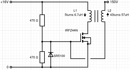
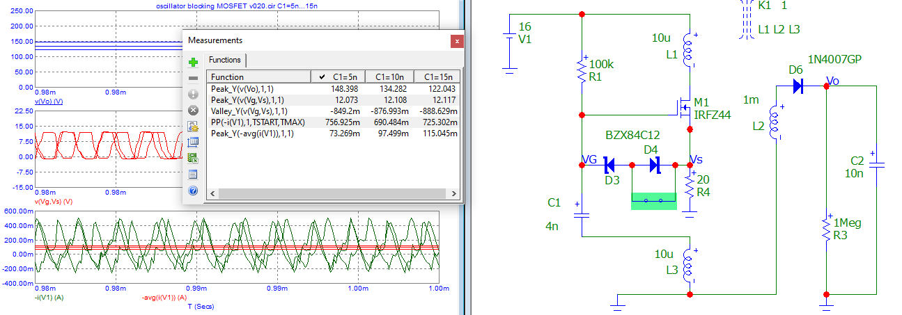
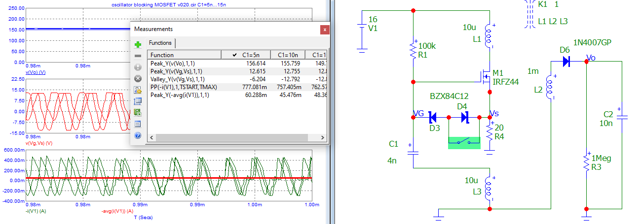
I am trying to build one of these using an air-core coil. I got it oscillating but have to cut power off after 4 seconds as it starts to heat up (can't hold it with my fingers.) The transistor is not on a heat sink.
I have searched everywhere (probably not everywhere, but extensively) and could not find answers to how to get it working without so much heat dissipating and a using MOSFET.
I started this project only to understand how it works using (cheap) oscilloscope and obviously safer voltages than what this could produce. Secondary as calculated is producing a voltage of 150V. The ocilloscope has a limit of 400V.
As per the schematic above, I am using a power supply which is rated 16V 625mA. When I checked current going to the circuit (using just an ordinary DMM) it is actually 2.38A. I don't know where this is coming from.
When the circuit oscillates I am getting 25V on gate-source if not more. Reading other comments on other threads, for full turn on of this MOSFET I need to have at around 10V on the gate even if thr MOSFET turns on at 5V and is capable of 20A.
When I connect a resistor between the power supply and the circuit to lower current and voltage, the resistor goes black in 2 mins and the circuit doesn't perform as expected.
What are other options to lower the voltage without dissipating extra voltage as heat? Say 13V?
The secondary circuit is open and no oscillation (or at least not intended oscillation) is happening on secondary. Is this required to get it working with lower power consumption?
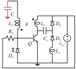
Back EMF from L1: There are suggestions to use a Zener diode to suppress this back EMF. A suggestion to utilize a back EMF snubber is mentioned here.
Figure 16. Regenerative snubber:
What would be reasonable values for this using a 12-16V power supply? Is Lx a simple choke?
Second picture I found here.
This option appears better as feedback is provided separate from oscillation. It doesn't protect the base from back EMF from L1, but a snubber could be used as stated above. Is this a simpler solution?
I don't have capacitance on source. Is that required? What value would be reasonable value/type?
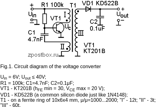
I have tried to build a simple Joule thief circuit as per MeTube videos and folks are getting amperage at 10mA using 1V battery. I've built one and could not get it lower than 35mA. Different topic, but I guess this is similar on a larger scale. Could it be lacking oscillation?
In article above "Wireless Energy Transfer" they claim 0.8A maximum drawn from the power supply and mine sucks 2.4A.
Parts used in this circuit were at hand. The other power supply I could use is a car battery I have at hand, but I can't imagine what power could be drawn from that using just 6 turns on primary L1. It could melt the speaker wire I used.
The IRFZ44N again was available at hand with great values of fast switching, high amperage capability and 50V should be sufficient if used correctly. Hoping if I could go over limits of normal transistor like 2N3904 or 2N2222 I should be fine, however it seems more complicated.
What I am expecting is power consumption below 1 ampere The lower, the better, since I'm not trying to transfer this power.
Since this circuit has been discussed from 2013, I hope someone would be able to provide a solution/idea how to improve this using MOSFET.
EDIT
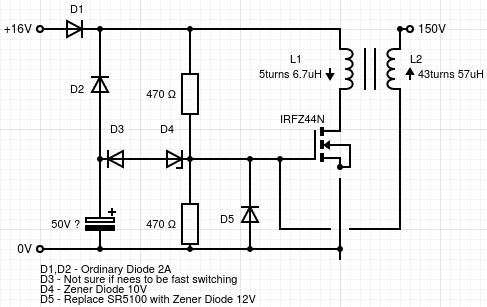
Idea, but unsure if it is a viable setup:
According to this video here , I need Snubber on primary L1.
Now with this setup I don't see voltage going above 8V on the gate and if it does, that should be regulated by Zener diode which connects Gate to ground.
With Snubber explained in that video, I should be fine with 4.7nF capacitor.
LED should light up if it is oscillating.
--- Final Edit ---
After a month digging through internet and trying to find answer to my own question, since very low contribution to this thread, I found out, that my primary was too close to secondary. It's short answer. Long answer won't be posted here.
Circuit redesigned from scratch.
Thanks to everyone who contributed to this thread and posted views and possible solutions.
127 views and 27 days since post created.

