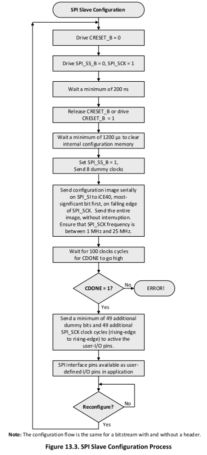
I am new to STM32 programming and design, and my first project is to get an STM32F413 to program a Lattice ICE40LP FPGA (also a new platform...) via its slave SPI configuration interface (page 17). The process is summarized in the below diagram. It seems straightforward and they even have pseudocode! However, a couple issues:
- If I drive the GPIO pins with software using the pseudocode in the spec sheet, the max SCLK speed I can get is ~500 kHz, which is below the minimum required.
- If I use the hardware GPIO, I don't see a way to manually set SCLK high in step 2, I can only send bytes which generates 8 clock ticks.
I guess the workaround is to initialize the SCLK pin as a GPIO for steps 1-4 (wait 1200 us), then initialize the hardware SPI so that it acts like a clock again. The code I'm using for that is below. In the little test loop that I have for toggling the SCLK pin, it doesn't toggle (tested with scope at speed and with an LED and debugger), but then later in the infinite loop (not shown) it acts like an SPI clock.
Is there some gotcha about initializing a pin as a GPIO and then reinitializing it for a different function? Did I cut and paste the GPIO initialization code incorrectly? I should note that the MX_GPIO_Init() function initializes other pins on GPIOB that are used for other functions on the discovery board. Any suggestions for other approaches and/or hints as to what I'm doing wrong would be appreciated.
  /* Initialize all configured peripherals -- GENERATED FROM IOC FILE */
  MX_GPIO_Init();
  MX_ADC1_Init();
  MX_DAC_Init();
  MX_DFSDM1_Init();
  MX_DFSDM2_Init();
  MX_FMPI2C1_Init();
  MX_FSMC_Init();
  MX_I2S2_Init();
  MX_QUADSPI_Init();
  MX_UART10_Init();
  MX_USART6_UART_Init();
  //  MX_SPI3_Init(); --- DEFERRING THIS TO LATER
  MX_USB_OTG_FS_PCD_Init();
  /* USER CODE BEGIN 2 */

  // program lattice FPGA
  // set up SPI SCLK pin as GPIO so I can keep it high
  GPIO_InitTypeDef GPIO_InitStruct = {0};

  GPIO_InitStruct.Pin = 12; // Using discovery board, which has this mapped to PB12
  GPIO_InitStruct.Mode = GPIO_MODE_OUTPUT_PP;
  GPIO_InitStruct.Pull = GPIO_NOPULL;
  GPIO_InitStruct.Speed = GPIO_SPEED_FREQ_VERY_HIGH;
  HAL_GPIO_Init(GPIOB, &GPIO_InitStruct);


  // set CRESET_B low
  HAL_GPIO_WritePin(ARD_D1_CRESET_GPIO_Port, ARD_D1_CRESET_Pin, GPIO_PIN_RESET);
  // set SS high
  HAL_GPIO_WritePin(ARD_D2_SS_GPIO_Port, ARD_D2_SS_Pin, GPIO_PIN_SET);
  // toggle SCLK for a while to test
  for(int i=0; i<10000; i++) {
      HAL_GPIO_TogglePin(GPIOB, 12);
      HAL_Delay(1);
  }

  // wait at least 200 ns
  for( int i=0; i<10; i++ ) ;  // assume 1 clk/instruction @ 16 MHz ~ 600 ns
  // set CRESET_B low
  HAL_GPIO_WritePin(ARD_D1_CRESET_GPIO_Port, ARD_D1_CRESET_Pin, GPIO_PIN_RESET);

  // wait at least 1200 us (2ms) to clear memory
  HAL_Delay(2);


  // set up SPI3
  MX_SPI3_Init();

  /* USER CODE END 2 */

