2
\$\begingroup\$

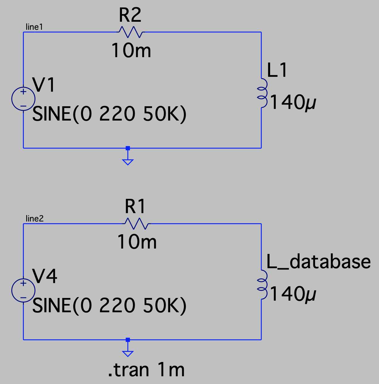
I am trying to simulate a simple RL circuit as shown below, the top one using inductor from the component library and the bottom one is picked from the database.

LTSpice Circuit Schematic

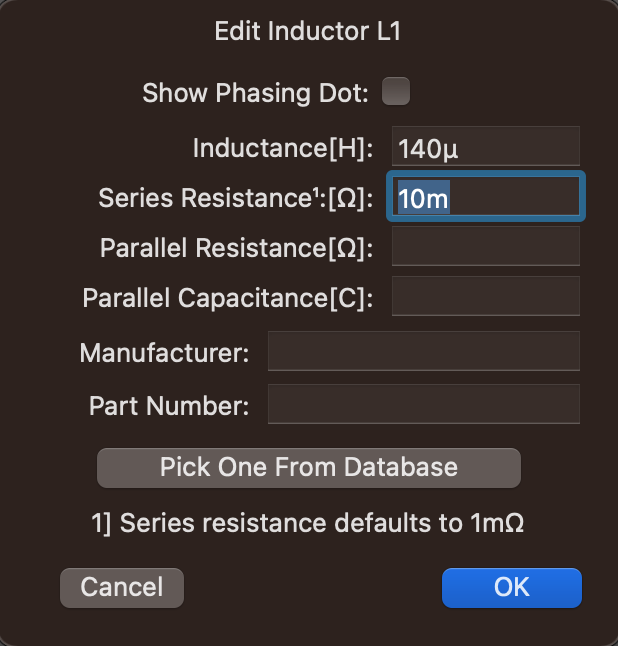
Below is the properties of L1 inductor

L1 inductor properties

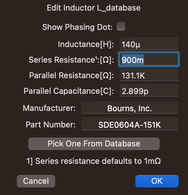
And below is the properties of the L_database inductor

enter image description here

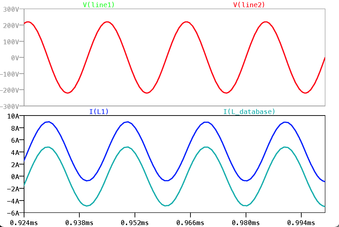
When I run the transient simulation I see the current in the L1 inductor does not have any negative value but the L_database inductor has the negative value.

enter image description here

The question is why the ideal inductor in LTspice is not showing the negative half of the current but the database inductor is showing correctly?

I am using the LTSpice XVII (Version 17.0.40) for MacOS.

\$\endgroup\$
1
  • 2
    \$\begingroup\$ If you look at the first few periods, you'll notice that the database inductor also starts off with almost no negative current, and if you enable the grid, you'll notice that the ideal one also is carrying a negative current, if you simulate for a longer duration you'll see both at about the same level. \$\endgroup\$
    – Arsenal
    Commented Apr 27, 2022 at 14:46

1 Answer 1

4
\$\begingroup\$

My big suspicion is that your sine wave voltage excitation is initially applied when the sine wave voltage is passing through 0 volts. So, assuming that you are, the inductors in both scenarios will "integrate" the applied voltage to produce their respective currents AND, what you will find is that the first current cycle of both inductors will be almost perfectly raised above 0 amps in their respective waveforms.

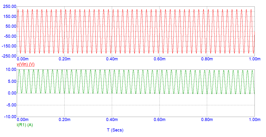
This is what will happen with an ideal inductor when you apply a sinewave at t=0. Here's my simulation of 140 μH in series with 0.01 Ω: -

enter image description here

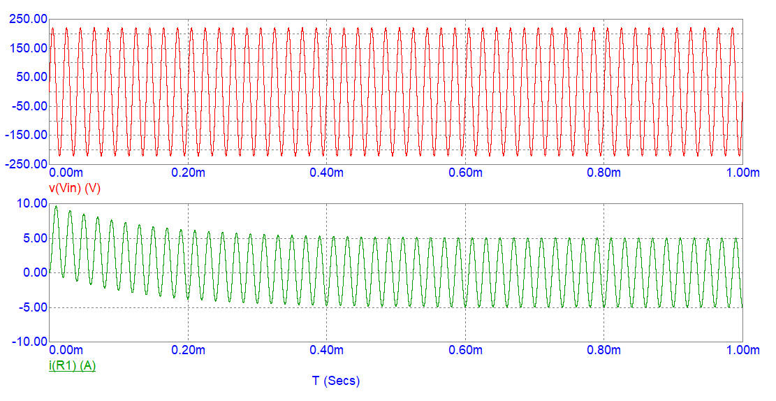
As you can see the current waveform starts pretty much all-positive and, by 1 ms, it might have dropped a little bit negative. If I made the series resistance bigger (like 1 Ω) you'll see that the current waveform eventually acquires roughly equal positive and negative amplitudes: -

enter image description here

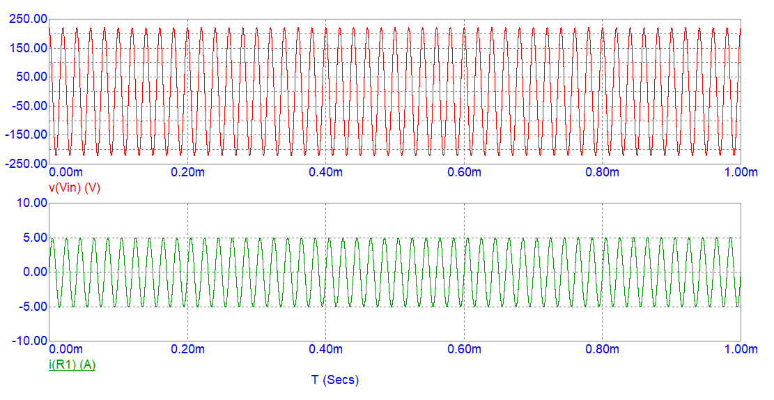
Instead, you should apply a cosine wave because that will naturally force the resulting current to be close to its long-term natural value: -

enter image description here

\$\endgroup\$

Your Answer

By clicking “Post Your Answer”, you agree to our terms of service and acknowledge you have read our privacy policy.

Not the answer you're looking for? Browse other questions tagged or ask your own question.