It's helpful to include a link to the datasheet even if, as you note, it doesn't explain the circuit operation.
Why is the video carrier frequency 38.9 MHz but the audio 33.4 MHz? On-air the audio carrier would normally be 5.5 MHz higher than the video, not 5.5 MHz lower?
This indicates that the 1st local oscillator (LO) is 38.9 MHz above the video carrier radio frequency, rather than below it. So the sound carrier, which is 5.5 MHz above the video carrier in the RF signal, swaps to below it after the first down-conversion. (This web page lists 10 analogue TV systems, 8 of which have the sound IF below the video IF.)
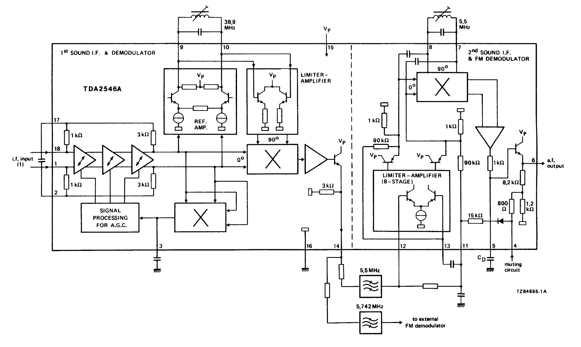
what is the left hand side doing? ... For example, is it just downconverting the signal? performing AM demodulation?
No AM demodulation here. The left hand side downconverts the sound carrier from 33.4 MHz in the first IF to 5.5 MHz for the second IF.
The 1st sound IF signal at 33.4 MHz enters on the left of the diagram through 3 stages of gain controlled amplifiers to provide the automatic gain control feature. It is then applied to a frequency mixer and mixed with a 38.9 MHz signal, of which more later. The output emerges from pin 14. The difference signal (38.9 - 33.4 MHz) is selected by the 5.5 MHz filter and passes into the 2nd IF and demodulator stages.
In a conventional dual-conversion superhet design we would have a 2nd LO to generate the 38.9 MHz signal to drive the mixer.
However, rather than using a LO this circuit picks out the 38.9 MHz video carrier in the REF AMP circuit (presumably reference amplifier) with an external tank (LC) circuit tuned to 38.9 MHz. The tank circuit is specified (figure 2) to have a reasonably high Q of 60 so will be able to pick out the video carrier from the wider bandwidth video signal and also maintain the signal during dips in the modulated signal.
Recovering the video carrier in this way means we don't have two signals (from the video carrier and the 2nd LO) at about 38.9 MHz (but differing slightly) leading to the sound carrier being mixed twice to 5.5 MHz giving distorted sound.
The 5.5 MHz signal can be used on its own for mono audio. It can also be used to carry a stereo sum signal (left + right) for analogue stereo operation. In this case the 5.742 MHz signal (at 33.158 MHz in the IF input) is used to carry a stereo difference (left - right) signal. This will require a similar demodulator stage. The demodulated sum and difference audio signals can then be fed to a stereo matrix circuit to recover separate left and right channels.
(The particular split of 5.5 and 5.742 MHz is/was used for analogue stereo sound transmission in some countries. The same principle can be used with different frequencies for other secondary sound carriers in other countries.)

