0
\$\begingroup\$

I bought a new ACS712 current sensor. VIOUT to ground is 2.560 V under no load conditions. This is very accurate as my supply is 5.12 V.

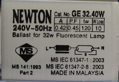
I plug in an old fluorescent tube that needs a ballast and starter to check the current.

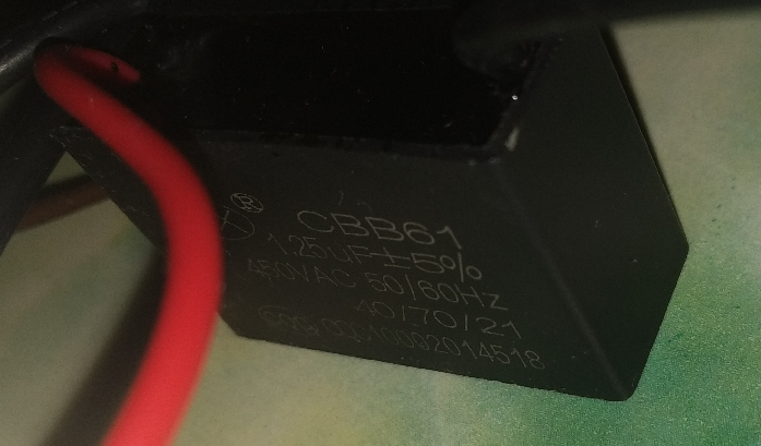
The photo of ballast

enter image description here

At first the reading, current and power factor is good as compared to a commercial wattmeter. I performed the power factor correction using a power factor capacitor and at this moment the reading is still good. After repeat the same demonstration several times, my current reading and power factor started to go bad and deviated more from the wattmeter reading.

I checked VIOUT of my current sensor again, and it is now showing 2.524 V on a 5.12 V supply. Is this normal? Will the arcing and current surge when I turn on the fluorescent light damage my current sensor? During turn on of the fluorescent light, my microcontroller will restart as the lamp flickers even though the brown out register has been disabled and I installed a small capacitor on the supply feed to the microcontroller.

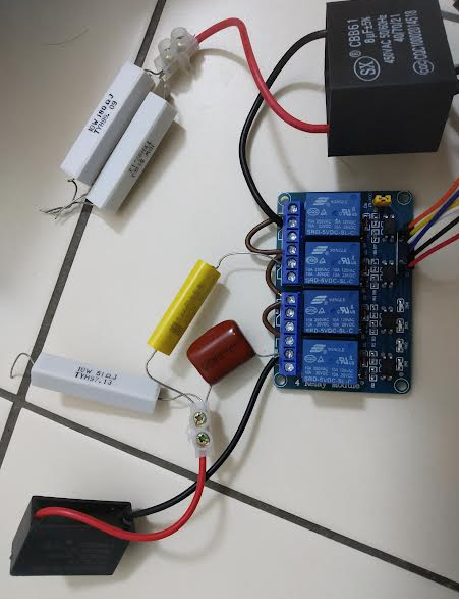
Update: repeated the experiment several times and I found that every time if the relay trigger on (which is connected to a 1.25 uF capacitor), it tend to shift the VIout value randomly and this value will remain even after power off and turn on the 5 V supply, is there any explanation on this or just pure coincident? As i tried with other new current sensor, if not connected to the PF capacitor load, the value can be as accurate as 2.56 V at 5.12 V at no load condition and remain accurate as Vcc/2 after connected to other load than capacitor. Below are the picture of relay and capacitor.

enter image description here

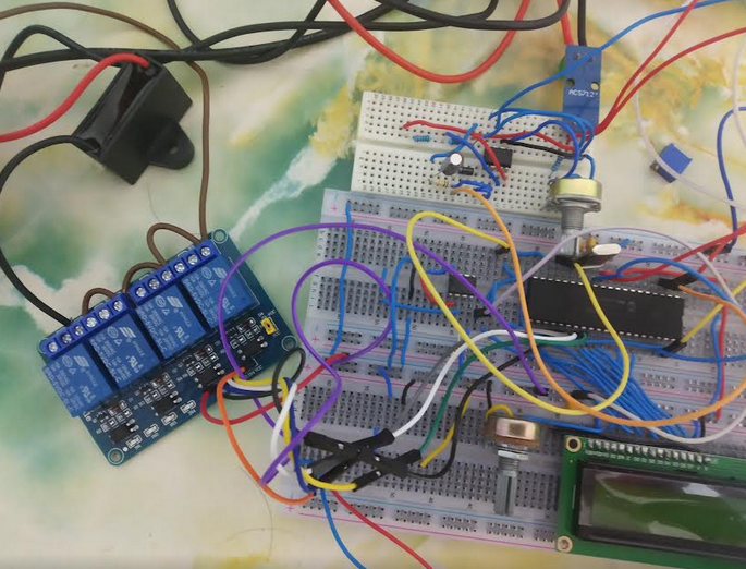
and the prototype enter image description here

\$\endgroup\$
11
  • 1
    \$\begingroup\$ What does the acs712 datasheet say? \$\endgroup\$
    – Kartman
    Commented Jun 26, 2022 at 7:55
  • \$\begingroup\$ It say viout=VCC/2 \$\endgroup\$
    – chuackt
    Commented Jun 26, 2022 at 7:58
  • 2
    \$\begingroup\$ To what tolerance does it say that? \$\endgroup\$
    – Andy aka
    Commented Jun 26, 2022 at 8:00
  • 2
    \$\begingroup\$ Note that "old" ballast (and some newer) generates big "EMI" int the nearest (0->100 cm). This can easily "reset" an MCU. \$\endgroup\$
    – Antonio51
    Commented Jun 26, 2022 at 10:11
  • 1
    \$\begingroup\$ Where are your power supply decoupling capacitors? Please post a picture that includes the ACS712 and all wiring. \$\endgroup\$ Commented Jun 26, 2022 at 19:43

1 Answer 1

1
\$\begingroup\$

I considered suggestion above that current sensor may have experience interference from nearby magnetic field. Apart from buying the shielding for testing purpose, I using a cheap solution like emf detector on google play that operate on hall sensor to pickup nearby reading and I got strong reading from energized relay and transformer, have shifted my current sensor far from those sources but my reading Vout reading still shifting when relay is turn on.

The apps on google play that operate on hall effect sensor in phone

enter image description here

Tested multiple time on capacitor load of 1 μF, 0.64 μF, 1.92 μF and 8 μF, Vout shifting randomly in the range of (2.56 V to 2.52 V) on a 5.12 V supply to current sensor Vcc. I measuring current of 0.3 A and this convert to voltage is equivalent to(0.185 mV/A*0.3 A=0.055 V) which shown this fluctuation can greatly affect my zero cross reading.

The solution I using to stabilize the Vout is by connecting current limiting resistor in series with PF capacitor as I been suspecting the random shift of Vout is due to in rush current as I been testing multiple load like fluorescent lamp, hair dryer and the Vout is still stick to original value after the power to the load is turn off (at no load condition). I only encounter this problem when relay turn on pure capacitor load.

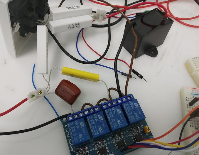
There 4 capacitor in the picture, 1 μF, 1.92 μF (1.25 μF parallel with 0.64 μF) connected to a 51 Ω resistor in series and 8 μF connect to a 33.15 Ω resistor in series for PF correction. I using different type of capacitor (different ESR) previously to test the result but non of them can stabilize the current sensor Vout.Regrettably, the value/choice of resistor connected is by trial and error until I found Vout value stable since I have no idea how to calculate the in rush current based on capacitor and resistor value, neither I have a high voltage probe to capture the in rush voltage across resistor which can be convert to current by using V=IR formula.

enter image description here enter image description here

\$\endgroup\$
0

Your Answer

By clicking “Post Your Answer”, you agree to our terms of service and acknowledge you have read our privacy policy.

Not the answer you're looking for? Browse other questions tagged or ask your own question.