0
\$\begingroup\$

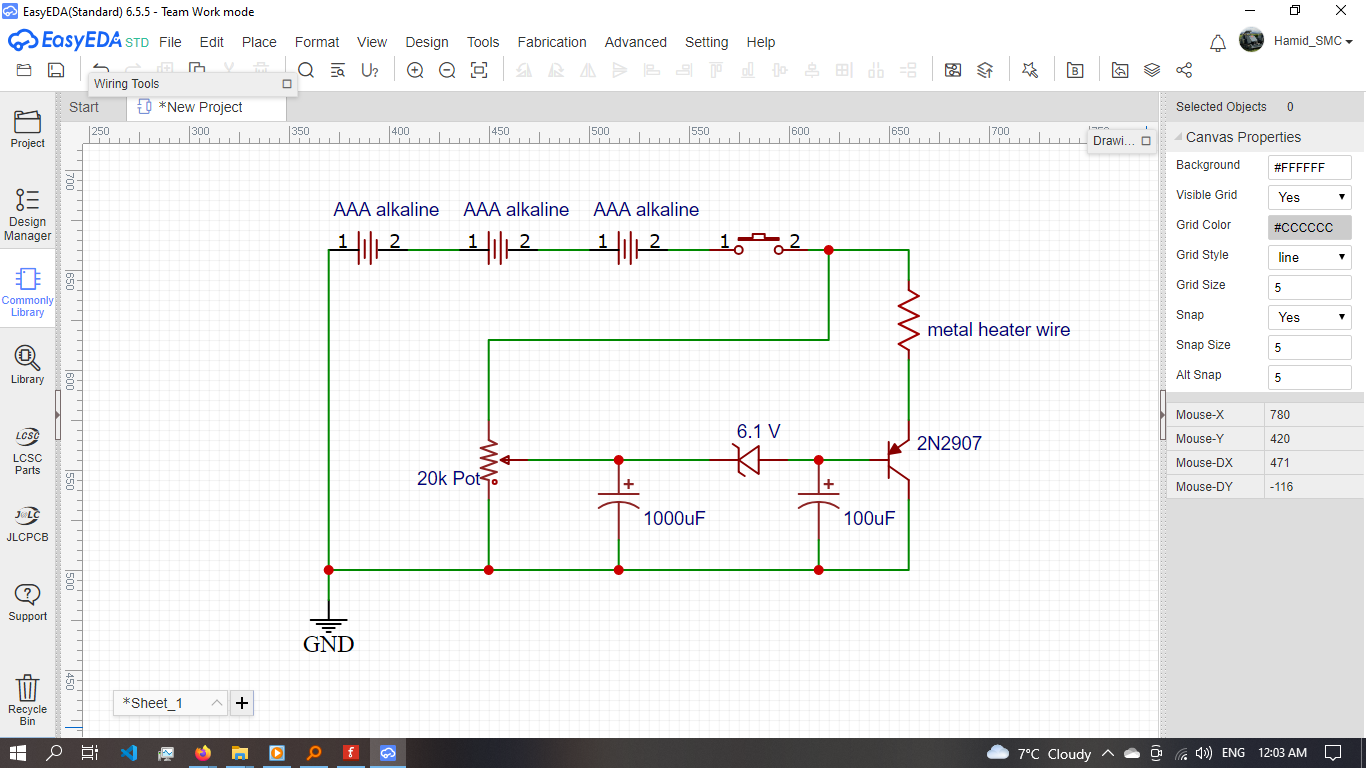
I'm trying to make On-delay circuit with passive components, I use 3 identical AAA alkaline batteries (4.5 v) and use PNP 2N2907 Bjt with 600mA Collector Current to heat(glow) up a small resistor wire

I use a 1000 uF capacitor and 20k Pot resistor for adjustable RC delay, Also I use 6.1v Zener diode however, when I press push button in my circuit the heating element does not even warm-up

following is my schematic

my question is:

Is Bjt not powerful enough to deliver current and heat up the element,

or is my schematic wrong and I should select another component?

if the current is not enough how can I add a wire coil inductor to charge on delay and push more current to the heating element?

enter image description here

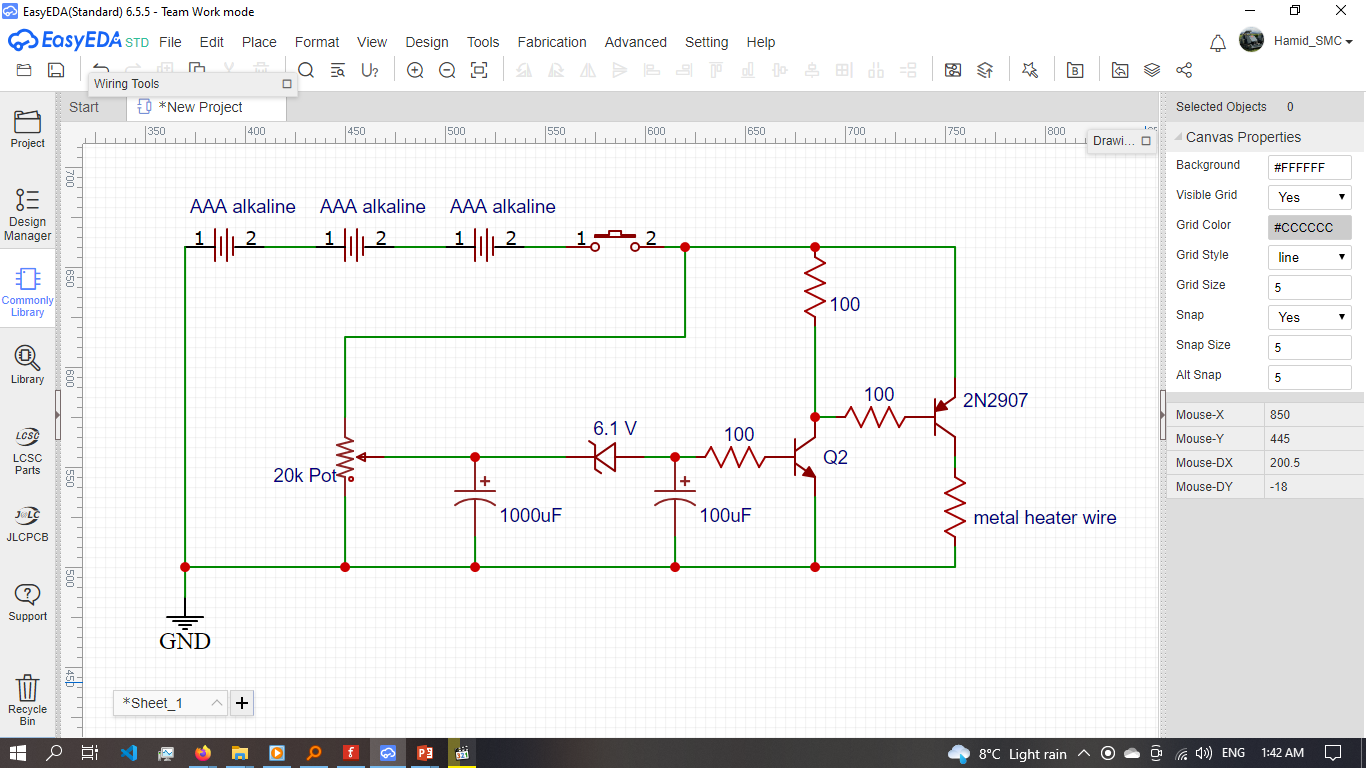
updated schematic

enter image description here

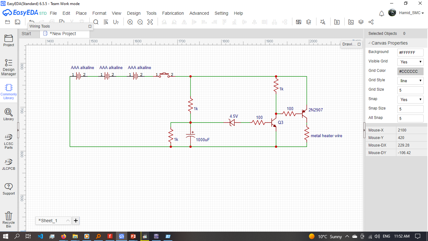
updated schematic base on new comments

enter image description here

\$\endgroup\$
9
  • \$\begingroup\$ Can you tell us how much current the heating element draws when cold and when hot, and how much delay you want? \$\endgroup\$
    – GodJihyo
    Commented Jul 15, 2022 at 13:30
  • \$\begingroup\$ @GodJihyo I think my heating element need around 1 Amp and want to delay not more than 10 seconds \$\endgroup\$
    – mehrdad
    Commented Jul 15, 2022 at 13:34
  • 1
    \$\begingroup\$ If you need 1A a 600mA transistor isn't going to handle it. And if it takes 1A when it's heated it will take a lot more when cold. \$\endgroup\$
    – GodJihyo
    Commented Jul 15, 2022 at 13:53
  • \$\begingroup\$ @GodJihyo can parallel two Bjt? \$\endgroup\$
    – mehrdad
    Commented Jul 15, 2022 at 13:56
  • 1
    \$\begingroup\$ The zener diode will never conduct. Its breakdown voltage is greater than the voltage from the batteries. Neither transistor will ever conduct. Also, if the batteries are connected as shown, they're backwards. Why do you want a 10 second delay? If you get the circuit working it won't do anything more than waiting 10 seconds before pushing the switch. \$\endgroup\$
    – stretch
    Commented Jul 15, 2022 at 15:58

2 Answers 2

3
\$\begingroup\$

You are trying to turn on a PNP transistor with a positive voltage from base to collector, to turn on a PNP you need a negative voltage from base to emitter.

Another problem is that you are using a 6.1 V Zener but your batteries only supply 4.5 V, so the Zener will never see enough voltage to conduct. You would either need higher voltage from the batteries or a different circuit altogether.

You could try an NPN transistor and swap the emitter and collector around, but you need one that will handle the cold current of the wire and enough base current to saturate the transistor which may require using another transistor as a driver.

Other options are a MOSFET or a relay, although a relay would add extra drain on the batteries.

You need to take the initial inrush current into account. A heating wire will have a low resistance when cold and then the resistance will increase as it heats up. This will cause a large current draw on startup than when in operation. You can deal with the inrush several ways, either use a device that can handle the maximum inrush current, or limit the inrush current.

\$\endgroup\$
4
  • \$\begingroup\$ the reason I use PNP is, that I couldn't find and high current NPN in the market, but I was suspicious about the Zener diode my capacitor not break it to drive the transistor \$\endgroup\$
    – mehrdad
    Commented Jul 15, 2022 at 13:37
  • \$\begingroup\$ I update the schematic \$\endgroup\$
    – mehrdad
    Commented Jul 15, 2022 at 13:44
  • 2
    \$\begingroup\$ @mehrdad You can't find a high current NPN, but you can find high current PNP? That sounds really strange to me, because NPN transistors are generally better in most respects than PNP equivalents, so they're much more common, especially for power transistors. \$\endgroup\$
    – Hearth
    Commented Jul 15, 2022 at 15:26
  • \$\begingroup\$ @Hearth price tag is the most factor of this project, if I could use the parallel PNP, still is much lower than the high current NPN or MOSFET or even N555 timer \$\endgroup\$
    – mehrdad
    Commented Jul 15, 2022 at 23:05
0
\$\begingroup\$

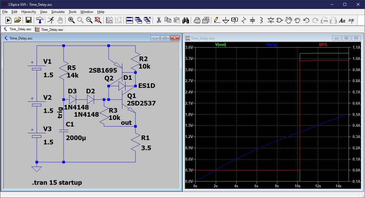
That time delay circuit needs a complete redesign, so here is my idea for something that should work. It uses an NPN/PNP pair as an SCR, so it will latch on and remain on as long as power is applied.

Time delay simulation LTSpice

\$\endgroup\$
2
  • \$\begingroup\$ price tag is the most factor of this project, although your circuit works it needs more components, then the price is more than N555 timer (robust solution) , can you check the new circuit update \$\endgroup\$
    – mehrdad
    Commented Jul 15, 2022 at 23:58
  • \$\begingroup\$ Simulate it or build it and find out. Or use an actual SCR. \$\endgroup\$
    – PStechPaul
    Commented Jul 17, 2022 at 23:27

Your Answer

By clicking “Post Your Answer”, you agree to our terms of service and acknowledge you have read our privacy policy.

Not the answer you're looking for? Browse other questions tagged or ask your own question.