0
\$\begingroup\$

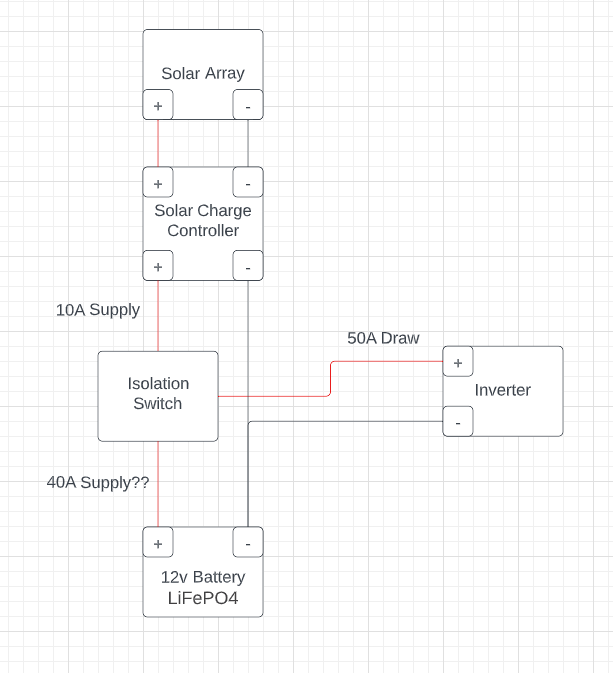
I want to understand what happens when a solar charger is charging the battery while the inverter is also drawing a load from the battery. Say theoretically the charge controller supplies 10A and the inverter needs 50A for its load. The way I see it, with the Inverter off, the 10A from the charge controller is going directly to the positive terminal of the battery. But when turn on the inverter and draw 50A, current cant flow both ways on the positive line from the switch to the batttery so I assume that the 10A from the solar charger goes to the inverter and the battery makes up the difference sending 40A. Is my thinking wrong? Also does it matter if positive lines meet at the isolation switch vs at the battery terminal?

This is a basic diagram without fuses ect of what I describe enter image description here
\$\endgroup\$

1 Answer 1

1
\$\begingroup\$

The solar charge controller would likely be designed to push as much power as available, up to the limit of 10 amps until the battery approaches full charge. The charge controller would likely monitor battery voltage, current and temperature and reduce current fed toward the battery as necessary based on these conditions and based on the battery rate of charge.

The load demands 50 amps of current, independent of the source of this current (the battery or the charging controller) and the battery sinks or sources any remaining current.

With the charge controller acting as a current source (in this condition) and the load operating as a current sink, the battery would provide the remaining current needed by the load. So, yes, 10 amps of current would be flowing from the charge controller to the load and 40 amps of current would be flowing from the battery to the load.

\$\endgroup\$

Your Answer

By clicking “Post Your Answer”, you agree to our terms of service and acknowledge you have read our privacy policy.

Not the answer you're looking for? Browse other questions tagged or ask your own question.