2
\$\begingroup\$

There was a great discussion back a few months ago on building a regulator for a dynamo. I have a similar challenge except the vintage motorcycle I'm restoring is a racing machine - neither lights not a battery (and no place for them). To the best of my knowledge there are no regulators made to control a dynamo without a battery with specs that match this dynamo.

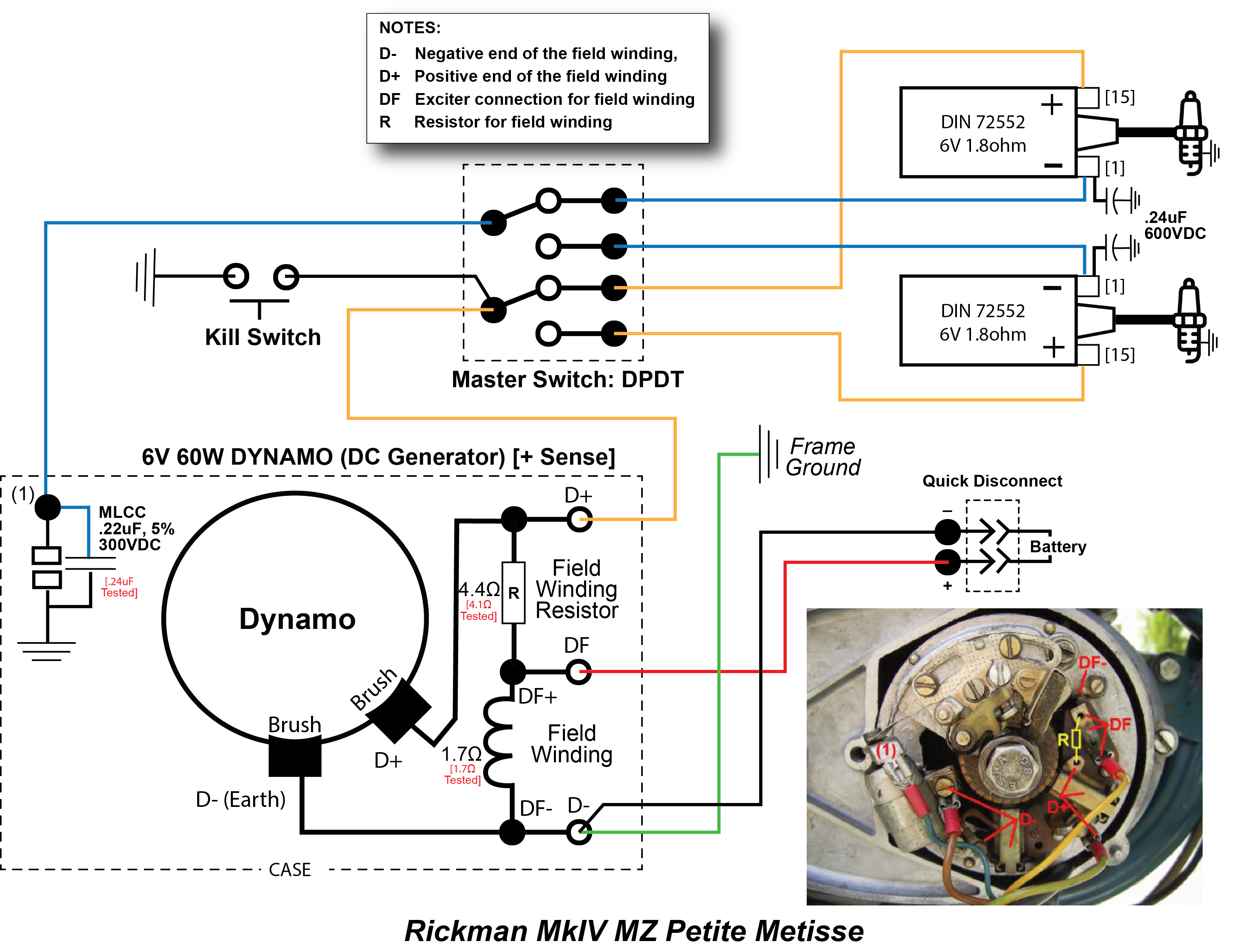
This non-permanent magnet dynamo is inside an East German MZ motor. It's a 6 V, 60 W Bosch type unit with a D+, DF, and D- connections. The dynamo has an integrated ignition system (points and condenser) driven by a cam on the armature shaft.

This motor is normally used in a motorcycle with lights + battery and the regulator would switch the field coil (resistance of 1.7 Ω) on an off with a Field Winding Resistor (4.1 Ω) bridging D+ and DF.

Since I only need ignition energy the dynamo won't have to do much work. The standard ignition coil's primary is 3 Ω (I also have a high output ignition coil at 1.6 Ω that I'd like to use to get a more intense spark).

If I stick with 6 V (which the ignition coils are designed for), and considering dwell time, powering the standard ignition coil would require a current of around 1.5 A. That will change based on motor speed, but from the experience of others running this motor the variation is about 0.2 A, so 1.3 A at higher speeds.

Here what I'd like to accomplish:

  • Voltage: 6 V output
  • Amperage: produce a stable 1.3 A to 1.5 A (or 2.8 A to 3.0 A for the high-output ignition coil)
  • Efficiency: generate as little heat as possible from the regulator
  • Size: approximately 50mm x 50mm x 25mm (I'd like to make a custom aluminum box and pot the final circuit given the vibration environment)

I am not certain how much current, if any, is needed to sustain the field in this dynamo.

I've been told this can't be done with this dynamo, but no one has explained why. I can understand why no commercially available solid state regulators would work since this is a one-off motor. I also have an existence proof - the motorcycle was raced with great success. Unfortunately, all of the electrical wiring was lost so I have nothing to go by... literally re-inventing the wheel.

My thanks for your advice on this one!

Wiring Diagram minus reg

\$\endgroup\$
6
  • \$\begingroup\$ What’s your input voltage range, desired output voltage and current? \$\endgroup\$
    – winny
    Commented Jul 22, 2022 at 21:22
  • \$\begingroup\$ 6v/2A out, input V range 2.5-6V \$\endgroup\$ Commented Jul 22, 2022 at 22:18
  • \$\begingroup\$ It would help greatly if you could trace out the pertinent wiring connections for this machine. Or you might be able to find one similar enough to use as a guide. \$\endgroup\$
    – PStechPaul
    Commented Jul 22, 2022 at 22:23
  • \$\begingroup\$ Will do... I'm trying to figure out how to post a pic. \$\endgroup\$ Commented Jul 22, 2022 at 22:33
  • 2
    \$\begingroup\$ The battery shown is a temp connection to energize the coil if it's lost residual magnetism; normally it wouldn't be there. These motors ran dual coils in an attempt to create redundancy if a coil failed or plug fouled. There switch is right in front of the seat. to select from A to B coil+plug, \$\endgroup\$ Commented Jul 23, 2022 at 0:35

4 Answers 4

2
\$\begingroup\$

The discussion you're referring to is this one: Building a solid state generator/dynamo voltage regulator, to replace an old mechanical regulator

If you have a schematic diagram that would be helpful. Regardless, it's possible to make an electronic regulator to control the field current and battery voltage fairly well. The proposal above for the Velo maintains a voltage appropriate for a 6V battery (I don't know how OP made out with it - he's in Oz so maybe message him?)

If you want to eliminate the battery you could use a large capacitor (that's what the old 'battery eliminators' are.) Alternatively, two Li-ion cells with appropriate protection (or a commercial Li-ion battery from someone like Zero Gravity) would also provide some stabilization for the coil voltage.

\$\endgroup\$
7
  • 1
    \$\begingroup\$ I recall ‘starter caps’ being in the 2000uF range or so. \$\endgroup\$ Commented Jul 22, 2022 at 23:33
  • \$\begingroup\$ I have a battery-less system on a BSA running a Tympanium rectifief/reg with a 5000uF cap - this is a permanent magnet alternator motor. A 2000uF 400V cap is still pretty beefy... don't know where I'd put it. \$\endgroup\$ Commented Jul 23, 2022 at 0:42
  • \$\begingroup\$ A 15 volt capacitor would be sufficient. And you can get a 12 volt 2.2 Farad capacitor for about $40: amazon.com/BULLZ-AUDIO-Digital-Capacitor-BCAP2-2/dp/B009XUNNZW/… \$\endgroup\$
    – PStechPaul
    Commented Jul 23, 2022 at 1:00
  • \$\begingroup\$ Definitely no room for something this large. \$\endgroup\$ Commented Jul 23, 2022 at 14:55
  • \$\begingroup\$ hacktastical mentioned the DVR2 regulator - I spoke with those folks and I was bummed that their regulator wouldn't work because the field coil resistance was too low. I'm puzzled by why this Bosch-type dynamo running without a battery seems to present such a challenge to a regulator. Beyond that I'm scratching my head as to how this motor was successfully raced in the early 1970s - some available tech made it possible. Maybe they bypassed the dynamo completely and ran a total loss battery. But these were long distance races and there's no mount anywhere on the frame. \$\endgroup\$ Commented Jul 24, 2022 at 13:40
1
\$\begingroup\$

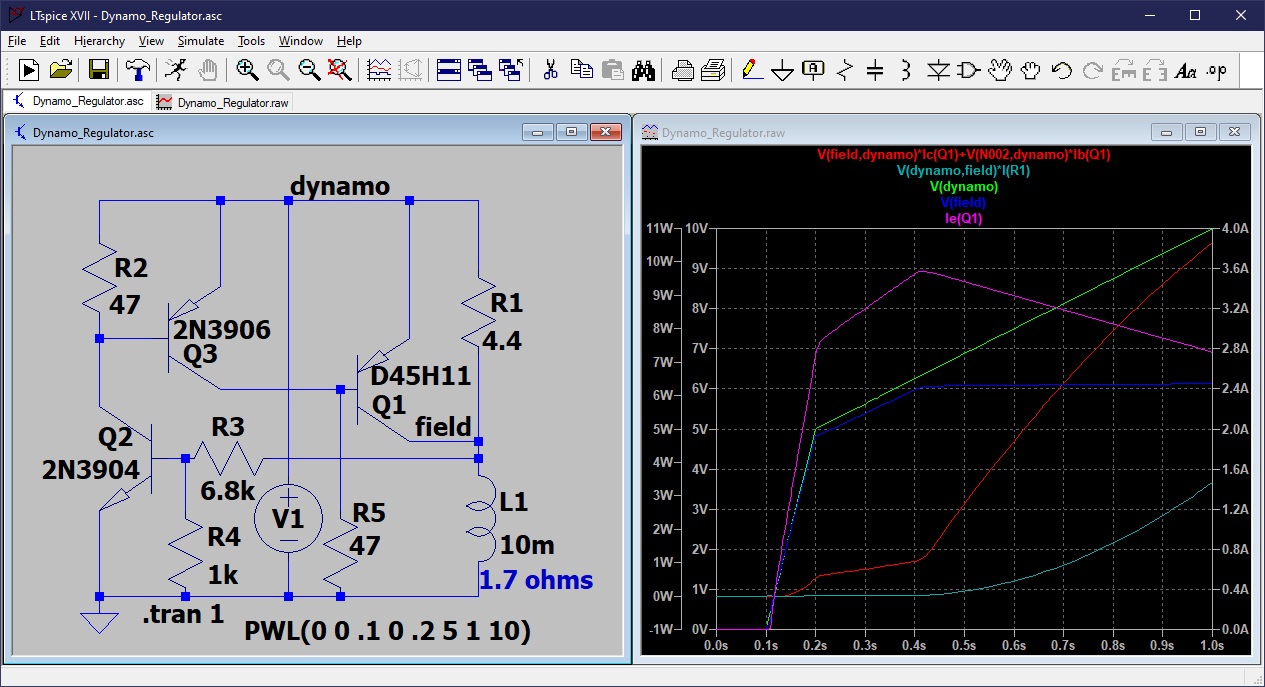
Here is a simulation of a voltage regulator that might work for this dynamo. It's a little hard to simulate a dynamo, so I used a time-varying voltage from 5 to 10 volts, and a circuit that regulates the voltage on the field to 6 volts. This uses the Vbe of a 2N3904 transistor to determine voltage, so it will be temperature sensitive. A more robust circuit could be designed.

Dynamo Regulator LTSpice Simulation

The power transistor Q1 dissipates a maximum of about 11 watts. In actual operation, however, it may dissipate less, as the output of the dynamo will drop when field current is decreased.

There are some motorcycles that simply use a 50 watt zener to regulate the voltage, relying on current limiting of the dynamo. See: https://www.electro-tech-online.com/threads/using-50w-zener-to-regulate-motorcycle-alternator.103828/

\$\endgroup\$
6
  • \$\begingroup\$ This is a simple and inexpensive solution. In my case, I'm presenting the dynamo with a fixed load (the ignition coil) which, to my naive electrical mind, is pretty insensitive to the cleanliness of the current it's getting. Here's a dumb question: since to me this looks like a current regulation challenge would a Linear Regulator with a cap to stabilize things do the job? \$\endgroup\$ Commented Jul 23, 2022 at 14:29
  • 1
    \$\begingroup\$ It seems to me that a zener solution, while simple, translates into having to dump a lot of heat. Since my load is small, isn't it better to only produce the energy needed thereby avoiding having to deal with excess heat? \$\endgroup\$ Commented Jul 23, 2022 at 14:41
  • 1
    \$\begingroup\$ The single power zener was used on a motorcycle that also had lights and other loads that used some of the current from the dynamo so it did not need to dissipate as much. Using field current to regulate output voltage is fairly efficient and probably much better than a simple linear regulator. The DC output of the dynamo is probably clean enough for ignition, but a good size capacitor (1000-10,000 uF) may help provide stability. A PWM design would be more efficient, but beyond the scope of this discussion. \$\endgroup\$
    – PStechPaul
    Commented Jul 23, 2022 at 23:46
  • \$\begingroup\$ Yep - a power zener would have a big job to do in this application. Is it logical to view my application as needing the regulator to limit the power output of the dynamo to a narrow band - essential feeding a steady current to the field coil across the RPM band? I'm with you on the benefit of a cap \$\endgroup\$ Commented Jul 24, 2022 at 13:52
  • 1
    \$\begingroup\$ The output of the dynamo is proportional to both RPM and field current. So you need to reduce field current as RPM increases. My imperfect simulation regulates the field voltage, but you would want to connect R3 to the dynamo output, which is what you want to regulate. \$\endgroup\$
    – PStechPaul
    Commented Jul 24, 2022 at 21:10
1
\$\begingroup\$

Easiest way is to buy a used MZ ts250 6-volt electromagnetic dynamo regulator; they appear on ebay fairly regularly, (as riders upgrade from the dynamo to magnetos with electronic ignition).

  1. The dynamo field coil is energised through the ignition warning light (which goes out when battery volts balance with dynamo output).
  2. As the dynamo charge volts rise, a spring-loaded field coil contact gets pulled towards its relay electromagnet, and begins charging the field coil through a wire wound resistor mounted on the dynamo. -Simultaneously, the battery reverse current cut-out (also spring-loaded) gets pulled towards its own relay electromagnet, bridging the dynamo output, charging the battery.
  3. As the dynamo output continues to rise, the field coil contact gets pulled closer to its relay magnet, until the contact hits an earth, cutting to electrical supply to the field coil....so the dynamo stops charging....
  4. causing the field coil contact magnetic force to weaken, so the field coil contact springs away from the earth contact & starts supplying power via the resistor to the field coil again... -all that happens really fast, so the regulator makes a buzzing sound!

http://www.sweller.co.uk/mz/electrics/dyn_wrdia.html

\$\endgroup\$
1
  • \$\begingroup\$ ........p.s step 1. is initial excitation/dynamo startup. ----I missed a step (see below)---- 1a. as the dynamo begins to spin, it starts generating power, this is routed direct to the field coil via the field coil contact which is in its 'resting position' \$\endgroup\$
    – bikerbrom
    Commented Sep 23, 2022 at 10:46
1
\$\begingroup\$

As a rebuilder of Magnetos and dynamos for vintage British motorcycles, I have tested all of the regulators available on the market as well as several homemade ones and I have yet to find one better than the one made by Dynamo Regulators in the UK. They can be used for either 6 V or 12 foot output depending how you wire it, but you must specify if you have positive ground or negative ground as they are two separate units. It does not get hot so it doesn’t need to be in the airflow and can be hidden very easily and includes a small stud with nut and lock washer to assist.

\$\endgroup\$

Your Answer

By clicking “Post Your Answer”, you agree to our terms of service and acknowledge you have read our privacy policy.

Not the answer you're looking for? Browse other questions tagged or ask your own question.