5
\$\begingroup\$

I derived the expression for the output voltage in this circuit, however, I have got the wrong answer. The problem is that I just know that it is the wrong answer because it's a multiple choice question and this was one of the wrong choices (hence I don't know why it is wrong - it seems correct to me!).

$$KCL_a:\frac{e_x-v_i}{R} + C\frac{dv_i}{dt} + \frac{e_x-v_o}{R} = 0$$ \$e_x = 0\$ because of virtual GND; so the equation becomes: $$\frac{-v_i}{R} + C\frac{dv_i}{dt} + \frac{-v_o}{R} = 0 \iff v_o(t) = -v_i + RC\frac{dv_i}{dt}$$

However it seems this is the wrong answer and I just don't understand why it is the case. Maybe it has to do with considering node a as it is? I think I can connect the wires into a single node at a because there is not element between.
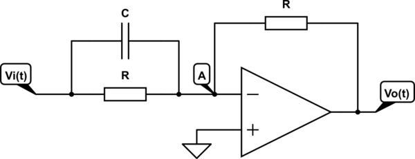
schematic

simulate this circuit – Schematic created using CircuitLab

\$\endgroup\$
2
  • 1
    \$\begingroup\$ With (ex-vi)/R and with (ex-vo)/R you are saying that a positive number means current is flowing away from node A, but with C(dvi/dt) you are saying that a positive number means current is flowing towards node A. So basically you got the capacitor backwards \$\endgroup\$ Commented Aug 29, 2022 at 18:57
  • \$\begingroup\$ @user253751 has identified for you the reason why one of your signs is wrong. \$\endgroup\$
    – jonk
    Commented Aug 29, 2022 at 18:58

2 Answers 2

4
\$\begingroup\$

Well, notice that no current flows into the negative terminal of the opamp. This implies that:

$$\text{I}_{\text{R}\space\text{||}\space\text{C}}=\text{I}_\text{R}\tag1$$

Using that we can see that:

$$\text{V}_\text{i}\cdot\left(\text{R}\space\text{||}\space\frac{1}{\text{sC}}\right)^{-1}=\frac{\text{V}_--\text{V}_\text{o}}{\text{R}}\tag2$$

And \$\text{V}_-=\text{V}_+=0\space\text{V}\$.

So, we get:

$$\text{V}_\text{i}\cdot\left(\frac{\text{R}\cdot\frac{1}{\text{sC}}}{\text{R}+\frac{1}{\text{sC}}}\right)^{-1}=\text{V}_\text{i}\cdot\frac{1+\text{sCR}}{\text{R}}=\frac{0-\text{V}_\text{o}}{\text{R}}\space\Longleftrightarrow\space\text{V}_\text{i}\left(1+\text{sCR}\right)=-\text{V}_\text{o}\tag3$$

\$\endgroup\$
2
  • \$\begingroup\$ Oh! I see... so my problem was my assumption over the parallel circuit. I was interpreting it like they were not being connected in parallel but into different input sources - which is obviously wrong. Thank you for making me see that! \$\endgroup\$
    – ludicrous
    Commented Aug 29, 2022 at 18:51
  • \$\begingroup\$ @ludicrous No, you can treat them as separate 2-terminal elements that just happen to connect to the same nodes. It works out the same way. \$\endgroup\$
    – jonk
    Commented Aug 29, 2022 at 18:54
1
\$\begingroup\$

The KCL for the A node is:

$$\frac{v_{_\text{A}}}{R}+\frac{v_{_\text{A}}}{R}+C\frac{\text{d}}{\text{d}t}v_{_\text{A}}=\frac{v_{_\text{O}}}{R}+\frac{v_{_\text{I}}}{R}+C\frac{\text{d}}{\text{d}t}v_{_\text{I}}$$

or,

$$\frac{v_{_\text{A}}-v_{_\text{O}}}{R}+\frac{v_{_\text{A}}-v_{_\text{I}}}{R}+C\frac{\text{d}}{\text{d}t}\left(v_{_\text{A}}-v_{_\text{I}}\right)=0\:\text{V}$$

or, with \$v_{_\text{A}}=0\:\text{V}\$,

$$\begin{align*} -v_{_\text{O}}-v_{_\text{I}}-R\,C\,\frac{\text{d}}{\text{d}t}v_{_\text{I}}&=0\:\text{V} \\\\ -v_{_\text{O}}&=v_{_\text{I}}+R\,C\,\frac{\text{d}}{\text{d}t}v_{_\text{I}} \end{align*}$$

You could put the above into standard form for a 1st order equation and try to solve it in the time domain. Or you could cast it into Laplace notation and solve for the transfer function:

$$\begin{align*} -V_{_\text{O}}&=V_{_\text{I}}+R\,C\,sV_{_\text{I}} \\\\ -V_{_\text{O}}&=V_{_\text{I}}\left(1+R\,C\,s\right) \\\\ \frac{V_{_\text{O}}}{V_{_\text{I}}}&=-1-R\,C\,s \end{align*}$$

Not sure if that helps. But there it is.

\$\endgroup\$

Your Answer

By clicking “Post Your Answer”, you agree to our terms of service and acknowledge you have read our privacy policy.

Not the answer you're looking for? Browse other questions tagged or ask your own question.