0
\$\begingroup\$

I need to turn ON/OFF a 220 VDC, 500W motor as well as changing its speed and reversing direction using a PLC and 3 relays as shown in attached drawing.

I am planning to supply 160 VDC for high speed and 35 VDC for low speed using a step-down transformer combined with a rectifier.

My question lies on the relay. What relay size should I use? Although I can find relays with a 10-15 A rating, most of them are rated in AC-1 (resistive load). According to my understanding, the rating will become much lower when used for DC inductive load, especially with a higher DC voltage.

Furthermore, I can only find DC ratings up to 48 VDC at most. I can't find any relay spec for 160 VDC. The best component I found so far is ABB's AF contactor series which has DC-13 specifications.

However, I was very surprised to find that their AF09-30-10-13 series which is rated at 25A AC-1 is only rated 0.27 A in DC-13 220 VDC. I was planning to just use a large oversized relay (80 to 120 A rating @ AC-1) for driving a high-voltage DC load, but I am not sure anymore after reading the ABB's spec.

I am all ears if anyone has any suggestions.

EDIT: Actually, both Relay Fast and rmRelay Run are handling AC current as they operate before the rectifier. Therefore, only Relay Fwd is exposed to DC current as its function is to reverse the motor's direction. However, that relay will only trigger before and after motor run. So it behaves more like a railway track that switches position before the train pass.

Having this behavior, do I still need to worry about the relay's arc issue as there is no breaking involved when current is flowing? Or are there any other issues that I am unaware of? If not, is it safe to just use a standard 15 A relay rated for AC-1 for the direction relay?

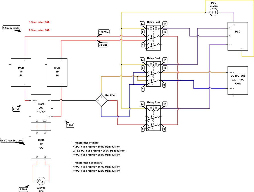
Wiring Diagram

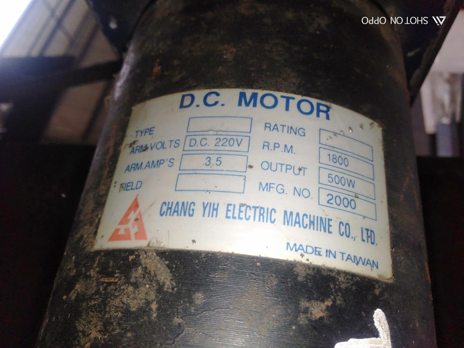
Motor Plate

\$\endgroup\$
8
  • 3
    \$\begingroup\$ Could you explain what AC-1 and DC-13 mean? That may be terminology specific to your subfield; I'm certainly not familiar with it. \$\endgroup\$
    – Hearth
    Commented Sep 5, 2022 at 12:58
  • 2
    \$\begingroup\$ It's quite normal for a relay or switch to have much lower DC ratings than AC ratings. Every mechanical switch will arc when opened or closed, and while an arc at AC will extinguish itself at zero-crossings, DC has no zero crossings and the arc can be sustained for an extended period. Relays rated for DC have to be able to either deal with such an arc, or extinguish it in other ways (or prevent it from happening at all, as with some vacuum or pressurized relays). \$\endgroup\$
    – Hearth
    Commented Sep 5, 2022 at 13:01
  • \$\begingroup\$ @Hearth There are zero crossings at all contacts. Can we consider this as AC circuit with the exception that polarity will not change? \$\endgroup\$
    – Jens
    Commented Sep 5, 2022 at 16:50
  • 1
    \$\begingroup\$ @Hearth you can check electrical4u.net/difference/… \$\endgroup\$ Commented Sep 6, 2022 at 4:06
  • 1
    \$\begingroup\$ @AlbertTobing Explain it in your question please. I'm not going to click a link to some site I don't recognise. \$\endgroup\$
    – Hearth
    Commented Sep 6, 2022 at 4:14

2 Answers 2

0
\$\begingroup\$

From ABB, look at GAE and GAF contactors, specifically for DC. For example:

https://new.abb.com/products/1SBL419025R8100/gae75-10-00-24v-dc

But please bear in mind that these are in essence single-pole contactors as they arrange multiple contacts in series to provide the breaking ability for DC (which tends to weld contacts together as there is no zero-crossing like in AC)

\$\endgroup\$
1
  • \$\begingroup\$ Yes, I am aware of the wiring in series which also applies to AF contactor. However, having need to use it as single pole contactor is inefficient and too costly \$\endgroup\$ Commented Sep 6, 2022 at 2:08
0
\$\begingroup\$

Dry contacts opening inductive current always arcs across the switch until below the holding current threshold which increases with a large gap. It is like an SCR that latches DC as AC provides a zero-crossing current to extinguish the arc.

The common solution was you use a BJT transistor Full bridge or a Triac full bridge with a smart controller to limit the slew rate of acceleration, braking and direction changes from AC rectified. speed control is done with PWM or phase control. Now Silicon Nitride or Other semiconductors may be more efficient. Start shopping for 1 Hp or more ESC, Electronic Speed Controllers or DC motor controllers with your specs for voltage and current and user functions.

This ** is not a solution but a cheap one for manual control of 400W motor reversible DC with auto soft start.

You just need one with an isolated PLC interface that might be 10x the price due to niche market pricing.

** Search "AC-220V To DC Motor Speed Controller Reversible Regulator Module Control-Switch"

\$\endgroup\$
3
  • \$\begingroup\$ Thank you for the suggestion. Interesting idea. Since I can't put any relay in the dc section, it means I have to purchase two of them, one for forward and one for reverse? Another concern is how reliable are they? They are all made in china by not well known brands \$\endgroup\$ Commented Sep 6, 2022 at 1:25
  • \$\begingroup\$ @AlbertTobing I think this will be your best option, unless you want to design your own H-bridge using MOSFETs or IGBTs. For 160 volts and 5 amps or so, the components would be pretty cheap, and you could use PWM for speed control without a separate 35 VDC supply. Otherwise, try kb-controls.com. \$\endgroup\$
    – PStechPaul
    Commented Sep 6, 2022 at 7:21
  • \$\begingroup\$ Albert You can use electrical4u.net/difference/… Call tech support for Siemens for DC-3 and PLC solution or call kb-controls for a PLC + DC motor control solution. I agree with @PStechPaul \$\endgroup\$
    – D.A.S.
    Commented Sep 6, 2022 at 15:54

Your Answer

By clicking “Post Your Answer”, you agree to our terms of service and acknowledge you have read our privacy policy.

Not the answer you're looking for? Browse other questions tagged or ask your own question.