0
\$\begingroup\$

Updated Again:

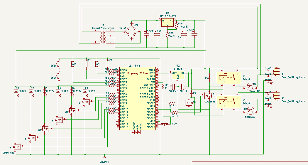
I have been working on this project for a few weeks now, with an end goal of having a control panel to power our two 120 V induction motors and 6 lights on the control panel using two 120 V outlets. The motors can take a maximum current of 8.8 A so I am attempting to use some current from one of the outlets to power a 12 V converter. This part of the circuit uses a flyback in conjunction with a bridge rectifier, capacitors, and a LM317 voltage regulator to get a 12 VDC output. This is needed for the LEDs I am using (which have a voltage rating of 12 V) and for the coils of the relays that I've chosen to use to activate the motors.

The only thing I'm wondering/concerned about with this part is its longevity. Will it have any trouble running for hours at a time? And if so, what actions should I take to rectify this?

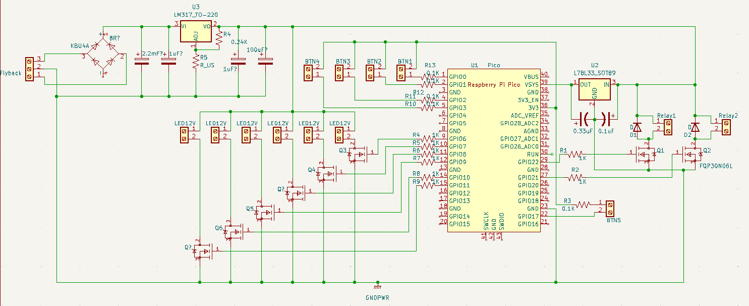
I redid the diagram in a more readable and understandable way, and have remade the PCB board with a ground plate on both sides connected to all of the 12V ground, and the ground from the base of the flyback. I also routed a ground from the pico to theground plane, and reoriented the power supply. Is this correct? Below is the full schematic without screw terminals:

Schematic Without Screw Terminals

Schematic With Screw Instead of external components

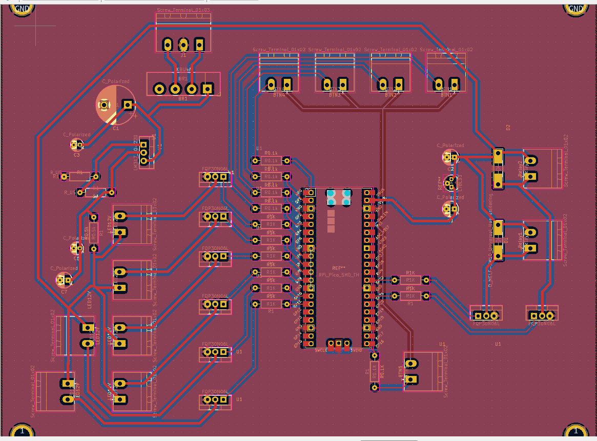
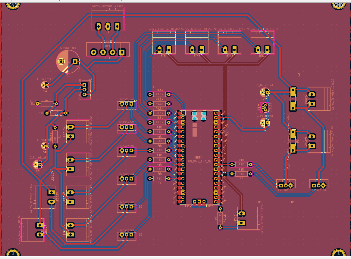
For the PCB boards, I believe I have done them correctly. I think I may need to space the FQP30N06L Mosfets apart more in order to fit the heat sinks, but other than that I think it should work. Would I need to do anything with the ground pin of the second 120V outlet, since im already connected to ground in a way? Should I add another screw terminal set and connect both grounds directly, or would that create a ground loop?

The PCB Without the Ground Plates

Full PCB

I also had a few additional questions. If these push buttons that I am using are rated for 660 V and 10 A would they even work with 3.3 V? At this point im considering using smaller ones. Lastly, is my spacing in between the ground and 12V traces going to be an issue if its too small, and if so how would I go about calculating that?

\$\endgroup\$
4
  • \$\begingroup\$ Spend some more time with your schematic to make it more readable. I can’t make sense of +VSW and -VSW. Supposedly AC, but goes through 1K resistors to TR1. That does not look sensible. You confuse the mains earth with the gnd reference for the pico. As drawn, the pico is likely to vapourise. What is the ‘flyback’? There’s no reference to it in the schematic. There’s way to many defects. Concentrate on one section at a time and resolve those issues. You might want to look at control boards for washing machines or suchlike to see how they layout the circuit board. \$\endgroup\$
    – Kartman
    Commented Sep 22, 2022 at 16:06
  • \$\begingroup\$ This layout has approximately 0 chance of working right. You need a ground plane. Route all the traces on the bottom, make top layer the ground plane. You can use vias and short "jumpers" for the bottom layer signals in the ground plane, but that's about it. The long thin traces will cause this thing to self-destruct in short order, and it'll be an EMI nightmare as well. \$\endgroup\$ Commented Sep 22, 2022 at 17:29
  • 1
    \$\begingroup\$ Since the switches are connecte to 3.3V, you need pull-down resistors on the GPIO pins to ensure that the pico will see a Low when the switch is open. \$\endgroup\$ Commented Sep 22, 2022 at 19:26
  • \$\begingroup\$ It is usually better to have the input switches connect to GND, and use pull-ups, which may be internal or external. The high power pushbuttons could pose a problem at low voltage and current, unless they have gold flashed contacts. \$\endgroup\$
    – PStechPaul
    Commented Sep 23, 2022 at 21:49

2 Answers 2

1
\$\begingroup\$

The Ground pins of the Pico should only be used to connect the Pico to Ground. Ground connections for the motors and LEDs should go directly to Power Supply Ground, and not pass through the Pico.

Your first schematic shows a negative power supply which is apparently not used. The LM337 and associated components (including half thebridge rectifier) can be deleted.

\$\endgroup\$
2
  • \$\begingroup\$ Thanks for the feedback! I attempted to do as you recomended, and In doing so I just connected the 4th pin of the bridge rectifier to ground. Is this the correct way to connect those, if only a positive 12 V source is needed? \$\endgroup\$
    – Ben Sailor
    Commented Sep 23, 2022 at 19:43
  • \$\begingroup\$ The unused terminal of the bridge rectifier should be left unconnected. You will effectively be using a full-wave rectifier rather than a bridge. All the Ground pins on the Pico must be connected to the power supply ground, but the ground connections must be routed so the ground current from other devices does not flow through the Pico. \$\endgroup\$ Commented Sep 23, 2022 at 21:12
0
\$\begingroup\$

Comments on today's schematic:

Please consider redrawing the power supply section of your schematic so that input-to-output flows from left to right, and the positive rail is above the negative rail. (Give that whole section a 180 degree flip, and orient the caps so that the positive rail is towards the top of the schematic and the negative towards the bottom.)

You have no ground pins connected on the Pico. You also have no ground connection to the U2 regulator. This needs fixing.

I am not sure why you have a 50 ohm resistor in series with the LM317 output. This is not a suitable replacement for a fuse. Also, as you engage LEDs and relays, the voltage will drop and you may end up starving the 78L33.

I will reserve comment on the PCB once the schematic is in better shape.

\$\endgroup\$
1
  • \$\begingroup\$ Thank you for the feedback! I had attempted to make it more readable by flipping the power supply around, but I guess that didnt have the desired effect. I will make all of those changes and update it a little later tonight. \$\endgroup\$
    – Ben Sailor
    Commented Sep 23, 2022 at 19:41

Your Answer

By clicking “Post Your Answer”, you agree to our terms of service and acknowledge you have read our privacy policy.

Not the answer you're looking for? Browse other questions tagged or ask your own question.