1
\$\begingroup\$

I want to amplify a 25 mVpp input signal with a source resistance of 1 kΩ to anywhere from 2.5 Vpp to 3 Vpp to drive an 8 Ω load (though at this point I am willing to sacrifice gain to just drive my load).

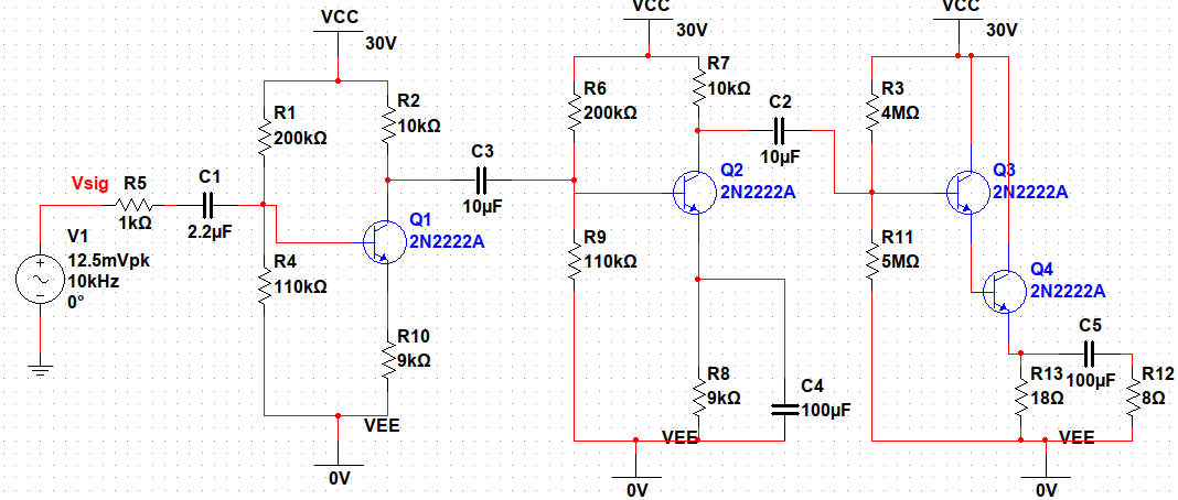
I successfully designed a CE-CE-Darlington pair amplifier configuration. The gain is what I want it to be with the exception of the issue of power dissipation across the secondary transistor. It exceeds the transistor's (2n9304 and 2n2222a) ratings and makes them release the magic smoke.

The circuit I have designed is below:

circuit

It might be odd but all I have are NPN transistors, specifically the ones I listed, so I can't use PNP BJTs though I wish I could.

Can I drive an 8 Ω load given my component limitations? I have managed to procure from an old bin some 2 W resistors and work around the resistors popping, but I am stuck at the secondary Darlington pair; I am not sure how to solve the issue. Any tips, tricks, or criticism would be appreciated.

\$\endgroup\$
4
  • 1
    \$\begingroup\$ You can use a class-A output stage that is built entirely from NPN BJTs. Driving that also entirely from NPN will require some crafted thinking. But it's all doable. \$\endgroup\$
    – jonk
    Commented Nov 18, 2022 at 4:48
  • 1
    \$\begingroup\$ An output transformer 10:1 would help to reduce the power dissipation in the output stage. \$\endgroup\$
    – Jens
    Commented Nov 18, 2022 at 5:02
  • 2
    \$\begingroup\$ Use a lower supply voltage, perhaps 12 V or maybe lower with suitable base-biasing for each of the 3 steges. \$\endgroup\$
    – user173271
    Commented Nov 18, 2022 at 8:40
  • \$\begingroup\$ The requirements to drive an 8 ohm speaker require design specs for current gain , impedance gain = Rin/8, distortion % and efficiency (opt.) If you would like my solution, pls include specs. \$\endgroup\$
    – D.A.S.
    Commented Dec 14, 2022 at 16:47

1 Answer 1

2
\$\begingroup\$

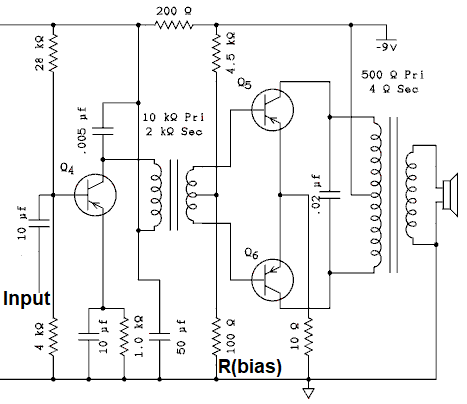
Many years ago, PNP germanium transistors were most common - used in imported battery-powered transistor radios. Shown below is the pertinent audio stages of such a radio: PNP germanium transistor push-pull audio schematic
You can substitute NPN silicon transistor (2N2222 type) with a minor biasing change, and a +9V supply rather than -9V supply. A much-higher supply voltage risks overheating the two output transistors.
You want almost 0.5V DC across \$R_{bias}\$ for silicon NPN transistors....\$R_{bias}\$ would be increased from 100 ohms to 270 ohms or perhaps 220 ohms is safer.
This is an efficient class AB audio amplifier with less heating than Class-A audio. However, those two audio transformers are now costly and more difficult to find. Scaling up power supply voltage to +30V is risky, since thermal design of this simple circuit likely cannot deal with really-hot Q5,Q6.


@jonk suggests another all-NPN approach. I have tested a more complex version of this arrangement and found DC biasing rather tricky, but it can be made to work.

\$\endgroup\$

Your Answer

By clicking “Post Your Answer”, you agree to our terms of service and acknowledge you have read our privacy policy.

Not the answer you're looking for? Browse other questions tagged or ask your own question.