2
\$\begingroup\$

I can't see this exact question answered elsewhere, so here goes...

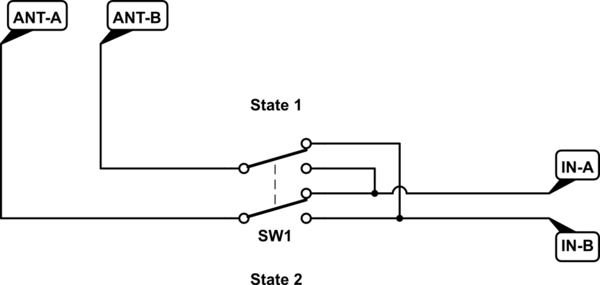
I want to build an antenna switch that'll allow me to SWAP two antennas between two antenna sockets on the radio. Common Ground, by the way... STATE 1 - Antenna A to input A and Antenna B to input B STATE 2 - Antenna A to input B and Antenna B to input A

I'm sure there's a very simple diagram to solve this but I can't get my head around it! I may just use a passive switch or possibly use a relay if there are too many losses in a switch.

Thanks very much.

\$\endgroup\$
2
  • 1
    \$\begingroup\$ What antennas are for, what kind of signal needs to be switched? I.e. signal power, frequency, etc. \$\endgroup\$
    – Justme
    Commented Dec 3, 2022 at 19:46
  • \$\begingroup\$ Sometimes switches can be done with MOSFETs. Two MOSFET in a series for each antenna (with opposite drain-source polarities). 4 in total. The Gates can receive high voltage to open and low to close. \$\endgroup\$
    – ee_student
    Commented Dec 5, 2022 at 20:55

2 Answers 2

3
\$\begingroup\$

Is it this arrangement you're looking for? You need a DPDT switch or relay. Whether this works for your signals is a different matter, and there can be a lot of issues for antennas.

schematic

simulate this circuit – Schematic created using CircuitLab

\$\endgroup\$
3
  • \$\begingroup\$ Yes, that's it! Thanks a lot. \$\endgroup\$
    – Martin
    Commented Dec 3, 2022 at 16:59
  • \$\begingroup\$ @Martin You should "accept" this answer by clicking on the checkmark next to it. \$\endgroup\$
    – ErikR
    Commented Dec 3, 2022 at 17:05
  • 1
    \$\begingroup\$ Please note that while correct as a diagram, it depends on the RF signal you need to switch if it can be done like this or not. \$\endgroup\$
    – Justme
    Commented Dec 3, 2022 at 19:47
3
\$\begingroup\$

Low voltage RF signal switching is not like other low power circuits. Mismatched wire/transmission line impedances, stray capacitances, and connector characteristics can combine for significant signal degradation. Switches and relays that are purpose-built for RF switching are relatively expensive, but perform much better.

Ham radio websites have lotsa information about this, links to vendors, etc.

Because pc boards are so cheap these days, one approach is to use a small DPDT relay on a pc board with stripline or micro-stripline path routing and standard RF connectors. This can reduce most of the impedance and shielding issues.

What signal frequencies are you switching?

Update:

The original question mentioned a radio, but not a transceiver. For that, there are many RF and antenna switch boxes on ebay. Two SPDT units mechanically ganged together will give you the DPDT function you want.

\$\endgroup\$
2
  • \$\begingroup\$ Hi - my radio transceiver has two antenna inputs; up to 75MHz, and 75-450MHz. One of my antennas is tri-band; good for 50, 144 and 433MHz. If I want to use it on 50MHz, I need to disconnect both antennas, then attach the tri-band antenna to the other socket, which is a bit of a faff. And whilst my 'swap-switch (or relay) solution' is far from elegant, any loss of received signal due to mismatch etc is far outweighed by local noise levels. As for transmit, I never run more than 5 watts power so I may even get away with it! Of course I'll be checking the SWR on the various bands. \$\endgroup\$
    – Martin
    Commented Dec 5, 2022 at 8:06
  • \$\begingroup\$ See answer udate. \$\endgroup\$
    – AnalogKid
    Commented Dec 5, 2022 at 20:22

Your Answer

By clicking “Post Your Answer”, you agree to our terms of service and acknowledge you have read our privacy policy.

Not the answer you're looking for? Browse other questions tagged or ask your own question.