6
\$\begingroup\$

I have a linear actuator that has a pot in it. I am reading the value of the pot on my uC and I am noticing that the values are fluctuating wildly when the pot is changing (both up and down). The values don't ever seem to stabilize. I use the moving average value to stabilize the value in software however this leads to errors. When I attach a normal pot to the uC I do not get any value fluctuations. All the systems are connected to the same power supply.

Question: Is there a better way in electronics obtain a stable reading from the pot in a noisy environment?

Edit: Servo City Linear Actuators

\$\endgroup\$
6
  • 2
    \$\begingroup\$ Do you have a schematic? That might explain why the pot isn't stable. You can also try to test the pot when it's disconnected, so that you're sure it isn't just that the pot's broken. \$\endgroup\$
    – user17592
    Commented Apr 6, 2013 at 16:29
  • \$\begingroup\$ 1. The pot's contact surface is probably either scraped off in parts, or covered by an oxide layer, thus causing the jumping values. Replace the pot. 2. A code-based method to address the problem is to reject outliers, i.e. any values more than a set amount away from the average of the previous n values. Would you want me to formulate this into an answer? \$\endgroup\$ Commented Apr 6, 2013 at 16:36
  • \$\begingroup\$ Ack, the entire system is rather complex so I can't really produce a schematic (sorry). There are steppers in the system as well but everything has decoupling caps. 2nd Its a new pot so I don't think the wiper is damaged as yet. Also I don't get noise when the motor is not moving (well very little anyways) \$\endgroup\$
    – user3045
    Commented Apr 6, 2013 at 17:35
  • \$\begingroup\$ This may be related: electronics.stackexchange.com/questions/51474/… \$\endgroup\$
    – jippie
    Commented Apr 6, 2013 at 18:01
  • \$\begingroup\$ Please add a datasheet and circuit diagram to your question. \$\endgroup\$
    – jippie
    Commented Apr 6, 2013 at 18:02

4 Answers 4

6
\$\begingroup\$

Are you digitizing a variable voltage produced by an analog potentiometer?

I have used gear like that and seen the jitter and flakiness in the values being read from the pots. In my experience it could be improved substantially by cleaning the potentiometers with compressed air and alcohol.

I suspect what the problem is that DC is naively being sent across the potentiometer, and then the divided voltage is sampled.

Audio designers know that significant DC currents flowing across potentiometers (which also carry audio) will add lots of scratchy, crackling noises when those potentiometers are moved (and maybe even when they aren't).

If I were designing a circuit which digitizes the position of an analog potentiometer (rather than the obvious approach of using a rotary or linear encoder), I would drop strictly an AC signal (from an oscillator) across the pot, with no DC component. This would then be rectified, peak-detected and digitized.

Another consideration is that cheap carbon pots are more noisy than ceramic, conductive plastic or wire wound units.

A very simple software technique to smooth values is exponentially-weighted smoothing. This is a beautiful trick which allows the smoothed value to depend on all prior values, without retaining a history of prior samples. (Familiar analogy: the charging of a capacitor is similarly exponential, and the current value depends on all the past currents. However, the capacitor has no memory, per se.) Looks like there is a Wikipedia page about it.

To implement exponential smoothing, simply keep track of the estimated value \$s\$ of the potentiometer (or whatever parameter \$x\$ you're sampling). The estimator is initialized with the first sample:

$$s_0 = x_0$$

Therafter, when a new sample is obtained, we replace the estimator with a linear blend of the existing and new value, where \$\alpha\$ is the blending factor (called "smoothing factor" in this situation).

$$s_t = \alpha x_{t-1} + (1 - \alpha) s_{t-1}$$

This can be conveniently rewritten like this:

$$s_t = (s_{t-1} - s_{t-1})^{\rightarrow 0} + \alpha x_{t-1} + (1 - \alpha) s_{t-1}$$

$$s_t = s_{t-1} - s_{t-1} + s_{t-1} + \alpha x_{t-1} - \alpha s_{t-1}$$

$$s_t = s_{t-1} + \alpha x_{t-1} - \alpha s_{t-1}$$

$$s_t = s_{t-1} + \alpha (x_{t-1} - s_{t-1})$$

In other words, the new estimate is the old estimate, plus a fraction of the difference between the new sample value and the old estimate.

If all the quantities are integers and \$\alpha\$ is some power of two constant, this is very easy to implement in code. For instance, suppose we take \$\alpha\$ to be \$1/4\$, so that we blend 25% new value, 75% estimator:

   /* C pseudo-code */
   s += (sample - s)/4;  /* optimizes to s += (sample - s) >> 2; */

   /* s returned to caller as the value */

Exponentially-weighted smoothing implemented as one line: subtract, shift right, accumulate.

\$\endgroup\$
7
  • \$\begingroup\$ So, a moving average then? \$\endgroup\$
    – user3045
    Commented Apr 6, 2013 at 20:53
  • \$\begingroup\$ A moving average is related but somewhat different. You keep a history of N samples and take their mean (or some weighted average). Samples older than N have no effect on the value. \$\endgroup\$
    – Kaz
    Commented Apr 7, 2013 at 1:12
  • \$\begingroup\$ I prefer this answer because of the suggestion of the AC component. \$\endgroup\$
    – user3045
    Commented Apr 7, 2013 at 3:24
  • \$\begingroup\$ This worked amazingly well for me in smoothing out a noisy pot: s += (sample - s)/4; \$\endgroup\$ Commented Dec 20, 2016 at 13:31
  • 1
    \$\begingroup\$ Exponential smoothing is a good technique. But if integer math is being used (quote: /* optimizes to s += (sample - s) >> 2; */), you lose resolution. E.g. if the pot value is actually raised or lowered by up to 3 from the previous value, the previous value will not be updated because 3 >> 2 is 0. It will only jump to the next position once the difference is 4 or greater. With a 10-bit ADC (such as found on ATmega328P), you will have actual resolution of 8-bit. \$\endgroup\$
    – Gene Pauly
    Commented Oct 26, 2020 at 10:07
3
\$\begingroup\$

Have you tried just putting a 100nF capacitor across the potentiometer wiper? That might just do the trick for you. This should have a "smoothing" effect, and bigger value capacitors will have a more pronounced smoothing effect.

\$\endgroup\$
3
  • \$\begingroup\$ Yea, I tried that; it failed. \$\endgroup\$
    – user3045
    Commented Apr 6, 2013 at 17:31
  • \$\begingroup\$ @kurtnelle do you have an oscilloscope you can use to have a look at how the signal varies for real? \$\endgroup\$
    – vicatcu
    Commented Apr 6, 2013 at 20:15
  • \$\begingroup\$ nope no oscilloscope (would really like one of those) \$\endgroup\$
    – user3045
    Commented Apr 6, 2013 at 20:44
0
\$\begingroup\$

It sounds like electrical noise from your motor is being coupled back to the potentiometer. If this is a DC motor linear actuator, try the following best practices as a first step:

  • Use twisted shielded cable for the potiometer excitation, wiper, and ground wires.
  • Use two pair twisted cable for the potentiometer - one pair for excitation and ground and the second pair for wiper and ground, with the grounds connected at the potentiometer. Use a differential amplifier at your board to reject common mode noise.
  • If practical, use twisted pair cable for the motor power leads
  • Use ~0.1uF ceramic capacitors across the motor leads (at the motor) and from each motor lead to the motor housing to mitigate some of the motor commutation-induced noise.
  • Avoid long parallel runs of motor power and potentiometer signal cabling to reduce crosstalk.

A better way to do loop closure in noisy environments is to use a quadrature encoder, as the signals between the linear actuator and your controller are digital and thus more noise immune. For very noisy environments, even digital encoder signals are handled differentially.

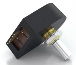
Encoders are available in many form factors, including ones that are interchangeable with potentiometers:

enter image description here

\$\endgroup\$
4
  • \$\begingroup\$ The ceramic capacitors are implemented in the linear actuator from the manufacturer. Twisted pair for the pot? Yikes but sounds fair. The differential amplifier sounds like a good idea. \$\endgroup\$
    – user3045
    Commented Apr 6, 2013 at 17:33
  • \$\begingroup\$ How is the potentiometer excitation voltage generated? Is it well regulated and clean? Use a scope to look at the excitation leaving your board and the excitation at the potentiometer (try both with and without the motor running). Since the pot wiper is single-ended at the moment (and inherently ratiometric), noise on the pot excitation will be coupled into its output. \$\endgroup\$
    – HikeOnPast
    Commented Apr 6, 2013 at 18:20
  • \$\begingroup\$ ask so that means it generates noise as it moves. So the only way to get the true value is to wait till it stops!? \$\endgroup\$
    – user3045
    Commented Apr 6, 2013 at 20:45
  • \$\begingroup\$ I wont be able to use a quadrature encoder here but I wish I could. \$\endgroup\$
    – user3045
    Commented Apr 7, 2013 at 3:25
0
\$\begingroup\$

I have a similar issue, DC PM motor, wirewound 10K, 10 turn pot. Using pot as a voltage divider, 5V out of uC (Arduino), get quite a bit of noise superimposed onto the position Arduino code to output the readings to the serial monitor. In this way, you can see what the digitized value the uC actually sees. In my case, the motors put a lot of noise onto the pot lines. Still, without the motors running, I noticed some other noise, after looking carefully at the values, it became obvious there was a 60Hz component to the noise.

By adjusting your sampling rate you can cancel most of it out.

\$\endgroup\$