0
\$\begingroup\$

I want to use a PNP transistor to switch off a load. I have a microcontroller that can give an output of 3.3V on the base of the transitor. The load can opparate at 3.3V also.

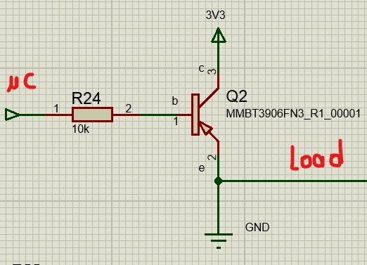
The idea is when the GPIO of the microcontroller is 0 the load is always on. When the GPIO is 1 the load is off. Can I use this circuit below, and what is the value recommended for the resistor?

enter image description here

\$\endgroup\$
4
  • 3
    \$\begingroup\$ Can I use this circuit below You can't. The load is grounded so it won't work. And the arrangement of the transistor is wrong. Have a look at here. \$\endgroup\$ Commented Jan 16, 2023 at 15:42
  • \$\begingroup\$ I searched the forum but I am still not sure about the right answer \$\endgroup\$ Commented Jan 16, 2023 at 15:45
  • \$\begingroup\$ Your transistor is upside down for one, so you'd be using it in the less effective reverse active mode. \$\endgroup\$
    – Hearth
    Commented Jan 16, 2023 at 15:49
  • \$\begingroup\$ @AnthonyJFeghaly You still need to specify what the load current compliance requirement is. And, although you say that the load can work from 3.3 V, that still doesn't state clearly that the load is only to be used with 3.3 V. Would it help you if the load used a higher voltage? \$\endgroup\$ Commented Jan 16, 2023 at 19:41

2 Answers 2

1
\$\begingroup\$

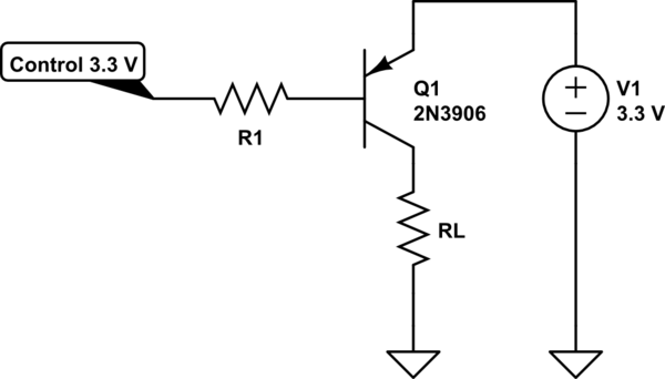
This is how to connect the PNP for high side switching. R1 has no value since that will depend on your load. For a LED, 10k is fine, if you want to switch something that draws more current, you will need to reduce it.

As the other linked question in the comments warns, if you increase the voltage at the emitter of the transistor (V1) above 3.3 V, the circuit is no longer appropriate and will damage your microcontroller.

The supply for the load and the microcontroller will need to share a ground for this circuit to work.

Note also that you will only be able to get the voltage across the load to within a few hundred mV of 3.3 V, not all the way to the rail.

schematic

simulate this circuit – Schematic created using CircuitLab

\$\endgroup\$
2
  • \$\begingroup\$ So will it be a normaly closed circuit?(when 0 from microcontroller the load won't run) And what values of resistance do you recommand for a 250mA load? Thank you! \$\endgroup\$ Commented Jan 17, 2023 at 9:56
  • \$\begingroup\$ When the control signal is 3.3V, the load will be off. When the control signal is 0V, the load will be on. For 250 mA load, somewhere around 910 ohms would be appropriate. \$\endgroup\$
    – vir
    Commented Jan 17, 2023 at 18:54
1
\$\begingroup\$
  1. Transistor is connected backwards, emmitter should go to your power source and collector to your load. (The arrow on the emitter is sort of depicting the direction of current. It flows from 3V3 to GND)
  2. Load should be between the transistor and the ground. On your circuit the transistor will basically short-circuit 3V3 to the ground. You need the current to flow through the load, not alongside it.
  3. 10k is too much. Good value probably would be about 100 - 500 Ohms. Proper way to calculate this is to look up the base current needed to fully open the transistor in datasheet.
\$\endgroup\$

Not the answer you're looking for? Browse other questions tagged or ask your own question.