1
\$\begingroup\$

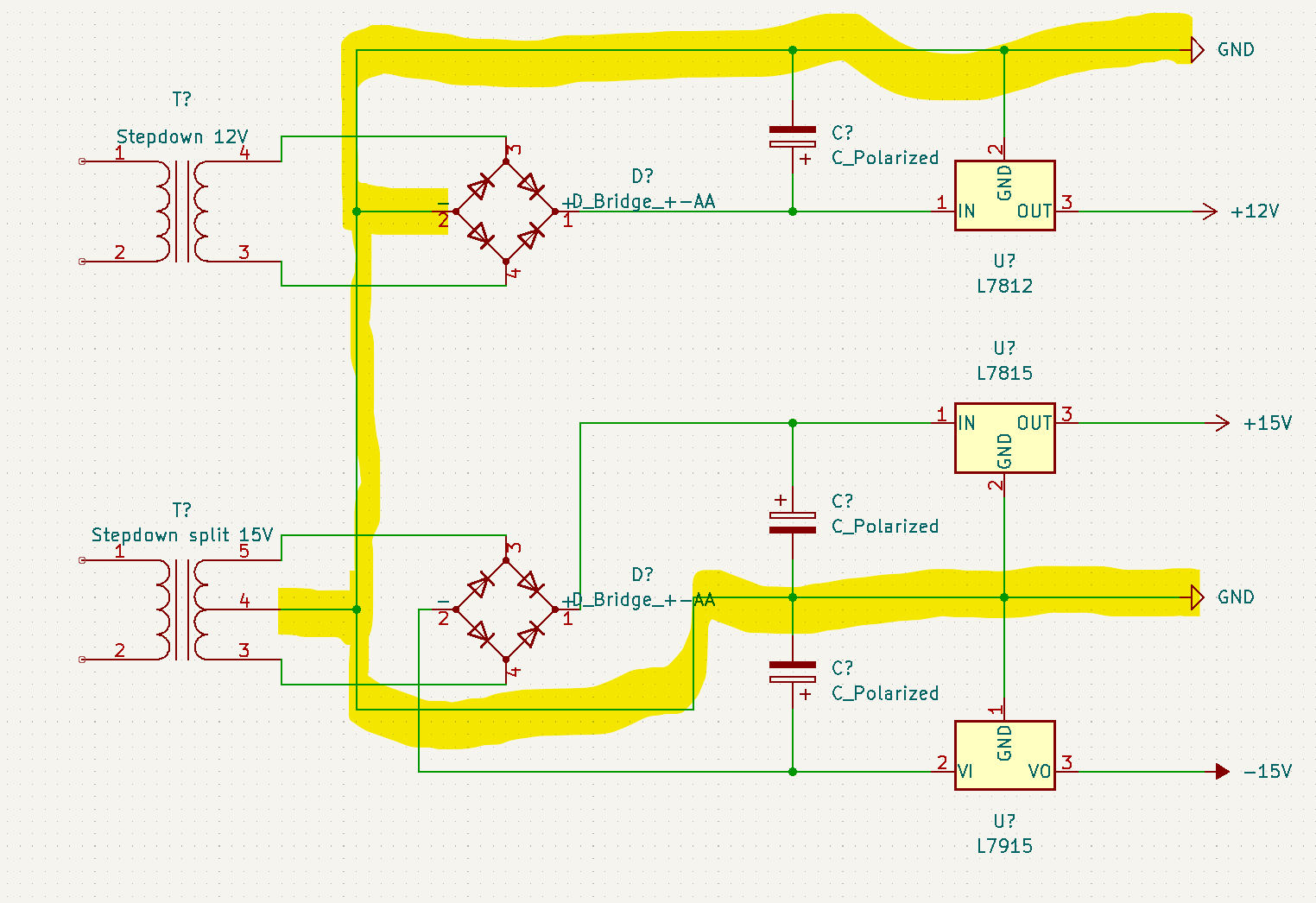
When and where you can have a common ground? In this case between 2 different transformers. The initial goal is to have:

  • One Ground
  • -15 V
  • +15 V
  • +12 V

The split 15 volt supply will be used for driving a few op amps and the 12 volt supply will be used to drive some LEDs. I like to keep the supplies for light and audio separated to reduce noise and interference.

My questions:

  • Can the grounds be connected together?
  • Will this design result in less noise?
  • Or will the LEDs still cause interference because of the common ground.

Here is a diagram to show what I mean. I have kept it simple, so no smoothing caps:

Circuit Diagram

\$\endgroup\$
3
  • 2
    \$\begingroup\$ That's fine. Noise depends on ground loops: keep the signal paths away from the LED load current path. \$\endgroup\$ Commented Jan 18, 2023 at 15:50
  • 3
    \$\begingroup\$ The polarity of the capacitor at the input of the L7915 is backwards. \$\endgroup\$
    – Audioguru
    Commented Jan 18, 2023 at 16:28
  • \$\begingroup\$ One way to ensure you don't 'mix ground' is to give the two different "ground" different net names while you do layout. Call one "12VGND" the other "15VGND" or whatever. In our layout software, I separate them with a zero-ohm resistor to trick the computer into thinking they are two different nodes. The zero-ohm can be removed at the last step. Doing this ensures the ground currents from the two systems do not intermingle and thus prevents (for the most part) any interference between the two sections of your design. \$\endgroup\$
    – Kyle B
    Commented Jan 18, 2023 at 16:30

1 Answer 1

1
\$\begingroup\$

Can the grounds be connected together?

Yes, but you don't have to. Unless you strictly want the lights to be non-isolated (e.g. for a vu-meter or a similar application) you can keep the grounds separated. Careful layout is required if the two grounds need to be connected together.

Will this design result in less noise?

Or will the LEDs still cause interference because of the common ground.

Noise is more related to layout. With an improper layout it's possible for the audio ground to elevate with the LED current.

\$\endgroup\$
2
  • \$\begingroup\$ Thanks for your answer. As I expected, the ground can be connected togheter, I was a bit hesitant about it because of the split 15 volts. The power will be used for VU meters and i tried to pick the power of the +15volt line which resulted in a buzz coming from the opamp, which never happened before. Almost sounding like op amp oscillation, but looking at your reply this seems to be a grounding issue? \$\endgroup\$
    – Lex Geurts
    Commented Jan 18, 2023 at 19:01
  • \$\begingroup\$ @Kwatskop as I indicated in my answer, layout is one of the key points here. If your LED's return current flows through audio ground then expect anything unusual. When I was designing valve amps I was having a similar problem as the valves require high voltage (200VDC min.); the filaments, post amp/eq sections and lighting (internal, indication, etc.) require low voltage (±15VDC), and I had to use a single transformer and its isolated windings for these supplies. Improper grounding brings 100 Hz hum, humming due to the grounding loops, etc. Search for grounding tips such as "star grounding". \$\endgroup\$ Commented Jan 19, 2023 at 11:09

Your Answer

By clicking “Post Your Answer”, you agree to our terms of service and acknowledge you have read our privacy policy.

Not the answer you're looking for? Browse other questions tagged or ask your own question.