0
\$\begingroup\$

Differential amplifier with a current source of 2mA and emitter resistor of 100Ω, each collector is connected to vcc = 12v. Collector resistor is 12kΩ for each resistor. It says differential input is applied between two bases. What is the input voltage Vid? (re = 50Ω) I noticed when we calculated the Ie current using Ie = 0.026/re we get Ic as 0.52mA. But 2xIc doesn't add up to 2mA which is given in the question. Any reason for that?
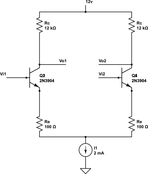
schematic

simulate this circuit – Schematic created using CircuitLab

\$\endgroup\$
1
  • \$\begingroup\$ the input voltage is an independent variable, i.e., you can control it. There's no calculation to help you determine it without other data known. \$\endgroup\$
    – Designalog
    Commented Mar 8, 2023 at 9:14

2 Answers 2

1
\$\begingroup\$

If Beta of the BJTs is really high such that IC is almost equal to IE, this structure cannot be biased properly because we expect 1mA to flow in each collector resistor when Vi1=Vi2. This means 12V drop across these resistors and since the supply is only 12V, Q2&Q3 VCE will become too low and hence the 2mA current source will have to get crunched.

If Beta of the BJTs is really poor, Ic will reduce and there is a chance for biasing the structure properly but I highly doubt this is the case.

Without fixing the DC operating point, we should not use it for amplification.

\$\endgroup\$
1
  • \$\begingroup\$ Yes - you are right. My recommendation: Change the current source to 1mA - and everything works. Perhaps it was a typing error only in the task description. \$\endgroup\$
    – LvW
    Commented Mar 8, 2023 at 11:32
0
\$\begingroup\$

In your question, you are mentioning a resistive element "re".

Do you think that re=Re in your task description? This would be wrong.

The quantity "re" is a BJT parameter. Unfortunately, some authors use such a symbol for the inverse transconductance (re=1/gm).

As we can see, this can lead to severe misunderstandings because, in fact, it is NOT a resistive quantity. It is based on gm - and as such it is 4-pole-parameter (but it carries the unit "Ohm").

EDIT: With a given value for gm=1/re the emitter current is known with Ie=26mV/re. This is a contradiction to the given value of the current source. All these considerations apply to the DC bias point only and have nothing to do with a signal input voltage Vid, which is applied externally,

\$\endgroup\$
4
  • \$\begingroup\$ It says re is the base emitter resistance. And Re is the emitter resistance which is 100Ω. \$\endgroup\$
    – O-Negative
    Commented Mar 8, 2023 at 9:39
  • \$\begingroup\$ How did you arrive at re=50 ohms? \$\endgroup\$
    – LvW
    Commented Mar 8, 2023 at 10:17
  • \$\begingroup\$ It was given in the question. \$\endgroup\$
    – O-Negative
    Commented Mar 8, 2023 at 10:37
  • \$\begingroup\$ Please, post the complete question. Perhaps the task is as follows: What is the DC value of a voltage difference that must be applied to the inputs for a required emitter current in ONE of the transistors which corresponds to re1=50 ohms? In this case, one BJT would have Ie1=0,5 mA and the second one Ie2=1.5mA. \$\endgroup\$
    – LvW
    Commented Mar 8, 2023 at 10:54

Your Answer

By clicking “Post Your Answer”, you agree to our terms of service and acknowledge you have read our privacy policy.

Not the answer you're looking for? Browse other questions tagged or ask your own question.