I am completely new to the world of amateur radio and I'm attempting to make a WWVB receiver and antenna. I currently have a large ferrite loopstick antenna built, based on this video. I got a measured inductance of ~10.12 mH and am using ~695pF for my circuit to resonate at 60kHz. I have been researching WWVB receiver designs and have found a few,
https://archive.org/details/73-magazine-1994-01/page/n13/mode/2up page 10
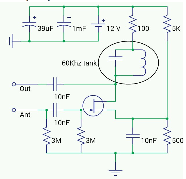
https://www.burningimage.net/clock/sensitive-60khz-receiver/
It seems like using a crystal is popular for highly selective receiver circuits, but I can't seem to find any 60khz crystals online. They also seem a bit pricy and harder to build/design. I was thinking of making a TRF receiver or something similar to that. The first article I linked seems to have a good design and I can follow how it works for the most part, but I wonder if I really need a circuit this complicated. They have automatic gain control which I don't understand at all and doesn't seem necessary for a simple receiver. The second design almost seems to good to be true due to its simplicity. It seems like no one has been able to get it to work besides the designer which worries me, but I wonder what your opinions are on the quality of the design. I think designing my own receiver might be necessary, but don't know that much about rf technology. Which is why I would be interested in your guy's opinions/tips on how I could go about doing this. Below this I wrote down what I know about designing receiver and some of the questions I have.
From my understanding I will need a good preamp stage, utilizing a n channel jfet to boost the signal enough to be used by ICs. Maybe a regenerative amplifier? or just a common source amplifier? I also have a few questions on how careful I need to be with the design of this stage. Do I need a proper ground using a copper plate to prevent noise or could I just use the negative terminal of my battery? Should I use a sampling coil on my ferrite antenna or just hook up the antenna directly to the preamp? Do I also need to keep my receiver circuit in a metal box to minimize outside noise? Does the n channel jfet I use really matter, or can I more or less use anything? I currently have some J112 and 2n5485 s. I also have a good set of 2n2222s 2n3904 2n3906 s etc, but those don't seem to be used in preamp stages because of their lower impedances (I think, please correct me if I am wrong).
So after my pre amp stage it seems like most designs implement a active band pass filter using op amps or transistor equivalents. I understand this part, but it seems like I can't use any opamp. Most of the op amp seem to have jfet input stages?
The next stage seems to be a demodulator which just involves a diode and a low pass filter. Then this signal is squared and sent off to a decoder. This seems straight forward, but if anyone has some helpful insights for this stage I would be all ears. From what I can tell these demodulator circuits can be made more complex for better results?
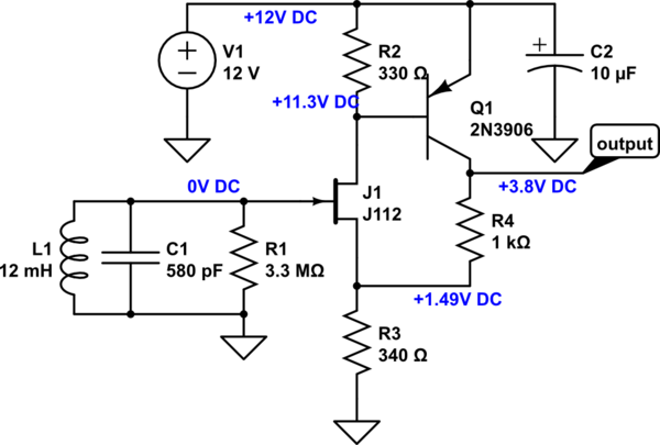
I ripped this design off another post to try and see if my antenna was even working properly,
 It seems to work, the output is a amplified 60kHz signal but doesn't seem to be modulated in the WWVB format which is weird. It looks like a 60kHz sine wave with a constant amplitude.
My main questions are,
- Does anyone have some good WWVB receiver designs? Preferably without utilizing crystals.
- How should I ground my circuitry?
- Should I shield my circuitry?
- How exactly should I connect my ferrite antenna to my receiver circuit? Using a sampling coil or just connect the resonant circuit directly? If I use the sampling coil I assume I wouldn't need to connect a capacitor to resonate at 60khz since it would sampling the resonant circuit already.
- What kinds of components should I use, specifically opamps and transistors. What specifications are important?
- Would prototyping on a breadboard cause problems because of the stray inductance and capacitance?
- Does my general idea of a receiver make sense or is there something I am missing?
Sorry for the long post. I have been doing a lot of research, but I'm still confused and trying to find some solutions. If you need me to clarify anything just let me know.

