2
\$\begingroup\$

I would like to modify a sewing machine motor so I can reverse its direction electronically.

Domestic sewing machine motors are universal motors with two wires – the input AC is connected through the field and armature windings in series, which means a stock motor will only run in one direction.

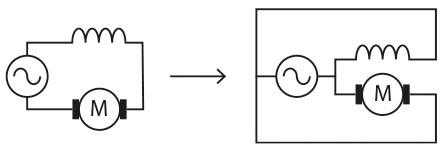
My plan is to physically modify a motor so the two windings are connected in parallel:

Motor rewiring

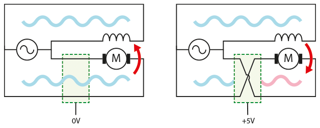
Then the motor can be run backwards by reversing the current through one winding:

enter image description here

What goes in the green box in this diagram? That is, how can I use a logic-level signal to reverse the polarity of the AC? Is there an AC version of an H-bridge IC or some similar component I can just drop in? Would it be easier to full-wave rectify the input and use a "normal" H-bridge to run it as a DC motor? This is a new area for me, so I'm not sure what to watch out for, or how these options might affect the motor's performance.

  • The motor will run on 220VAC at, say, 1A.
  • I don't expect it to change direction frequently, or while the coils are energised, but the circuit should be able to survive if those things do happen.
  • I know there are some mechanical challenges too, but assume I can resolve those.
\$\endgroup\$
4
  • \$\begingroup\$ Have you considered a relay with DPDT contacts? \$\endgroup\$ Commented Apr 21, 2023 at 14:49
  • \$\begingroup\$ Is it a particular sewing machine? Many modern sewing machines use stepper motors. \$\endgroup\$
    – jonathanjo
    Commented Apr 21, 2023 at 15:30
  • \$\begingroup\$ The circuit you're looking for is called an H-bridge... or would be, if it was for DC \$\endgroup\$ Commented Apr 21, 2023 at 17:16
  • \$\begingroup\$ It would be best not to "plug" the motor (reverse it when it's screaming away in the opposite direction). Maybe you can add an interlock of some kind to prevent that. \$\endgroup\$ Commented Apr 21, 2023 at 17:55

4 Answers 4

7
\$\begingroup\$

Make your life easier. Don't rewire the motor to be more like a DC motor or something. Just reverse the motor the way universal motors are normally reversed.

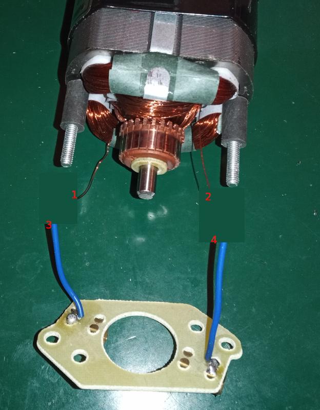
Here's one of my sewing machine motors:

enter image description here

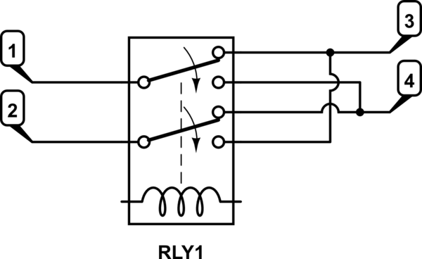
Connect it to a double pole, double throw (DPDT) relay like this:

schematic

simulate this circuit – Schematic created using CircuitLab

You can use an electromechanical relay (one with a coil in it) or a solid state relay (no coil, all electronic.)

In either case, you will need a relay with contacts rated for 240VAC and more than 1A.

The rating for the switching side of the relay will depend on the circuit that will control the motor. If you are using an Arduino (or other 5V microprocessor,) then you'd want a relay that can be driven be 5V and (very) low current.

The electronics will have to go outside the motor housing. I don't think you'll find a suitable relay that will fit inside.

Since you are playing with 240VAC, make sure to properly insulate your wiring and use grommets where the wires pass through the metal. Be sure to insulate the switching circuit and provide isolation for the switching side (whatever is driving the relay.)


Rewiring the motor to put the coils in parallel is problematic. The coils were designed with the understanding that the coils will be in series, so each only has half of the 220VAC across it. Putting them in parallel exposes each to the full 220VAC. Because of the higher voltage, more current will flow through each coil when they are in parallel. That's probably a bad thing.


Be very careful when working on the insides of a sewing machine motor. I just learned the hard way that the windings in some of them use aluminum wire. If you break a connection, you cannot solder it back together with normal solder.

Aluminum breaks easier than copper and can't be soldered easily. I tried, but couldn't do it. The connections inside the motor are crimped rather than soldered. The blue wires in the picture can be soldered, but not the motor windings.

\$\endgroup\$
2
  • \$\begingroup\$ I see: you are reversing the current through one winding, but without putting the coils in parallel. \$\endgroup\$ Commented Apr 21, 2023 at 17:18
  • 2
    \$\begingroup\$ Putting a series wound motor's coils in parallel would be a VERY BAD idea : this above (reverse either, but leave them in series) is the way to do it. (Parallel would put the full 220V across a winding rated for about a tenth of that voltage. Smoke, flame, molten copper likely) \$\endgroup\$
    – user16324
    Commented Apr 21, 2023 at 21:32
2
\$\begingroup\$

schematic

simulate this circuit – Schematic created using CircuitLab

To reverse the motor just reverse either the field or the rotor winding. This will preserve the characteristics of the series would motor and save you other problems.

SW1 can be a toggle switch or a relay.

\$\endgroup\$
1
\$\begingroup\$

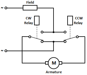
The motor's armature or field leads are to be interchanged to effect motor direction reversal.

Two electromagnetic relays would do, energising one or the other, to obtain the required direction of rotation.

Here's the schematic for interchanging the armature leads.

enter image description here

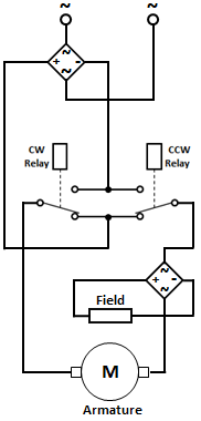
In the case of a DC series motor, to be operated on AC, two bridge rectifiers would be required.

enter image description here

The field rectifier ensures that the polarity of the field supply remains the same irrespective of the motor direction.

\$\endgroup\$
0
\$\begingroup\$

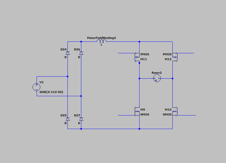
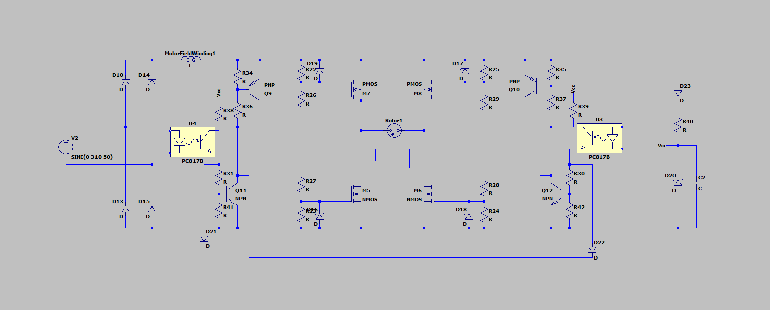
As all other answers, I suggest to not rewind the motor and work with motor connections. As your question mentions to "electronically reverse", and previous answer uses switches or relays, following schematics uses a series winding with a rectifier, and a H bridge to reverse motor brushes.

enter image description here

This example uses high side PMOS to avoid a boost supply. Also you can explore to control the speed/torque if you use PWM signal for the optocouplers signals.

enter image description here

\$\endgroup\$
5
  • 1
    \$\begingroup\$ That's certainly a brave but complex solution. Are you proposing that the H-bridge alternates rotor polarity in sync with the mains? If not then the fact that the field winding is alternating and the rotor is not will mean that the rotor torque will reverse on every half-cycle and it will not turn. You might be able to get it to work by moving the field winding inside the rectifier. \$\endgroup\$
    – Transistor
    Commented Apr 23, 2023 at 17:33
  • \$\begingroup\$ @Transistor: You are right. It can be done, but I will edit to shift the field winding for more simple approach. \$\endgroup\$
    – Bravale
    Commented Apr 23, 2023 at 22:17
  • \$\begingroup\$ It looks like Q9 and Q10 have E-C reversed. \$\endgroup\$
    – PStechPaul
    Commented Apr 23, 2023 at 22:31
  • \$\begingroup\$ @PstechPaul: corrected. \$\endgroup\$
    – Bravale
    Commented Apr 24, 2023 at 15:19
  • \$\begingroup\$ Good thing there's an air gap in the stator's magnetic path. \$\endgroup\$
    – greybeard
    Commented Apr 24, 2023 at 15:21

Your Answer

By clicking “Post Your Answer”, you agree to our terms of service and acknowledge you have read our privacy policy.

Not the answer you're looking for? Browse other questions tagged or ask your own question.