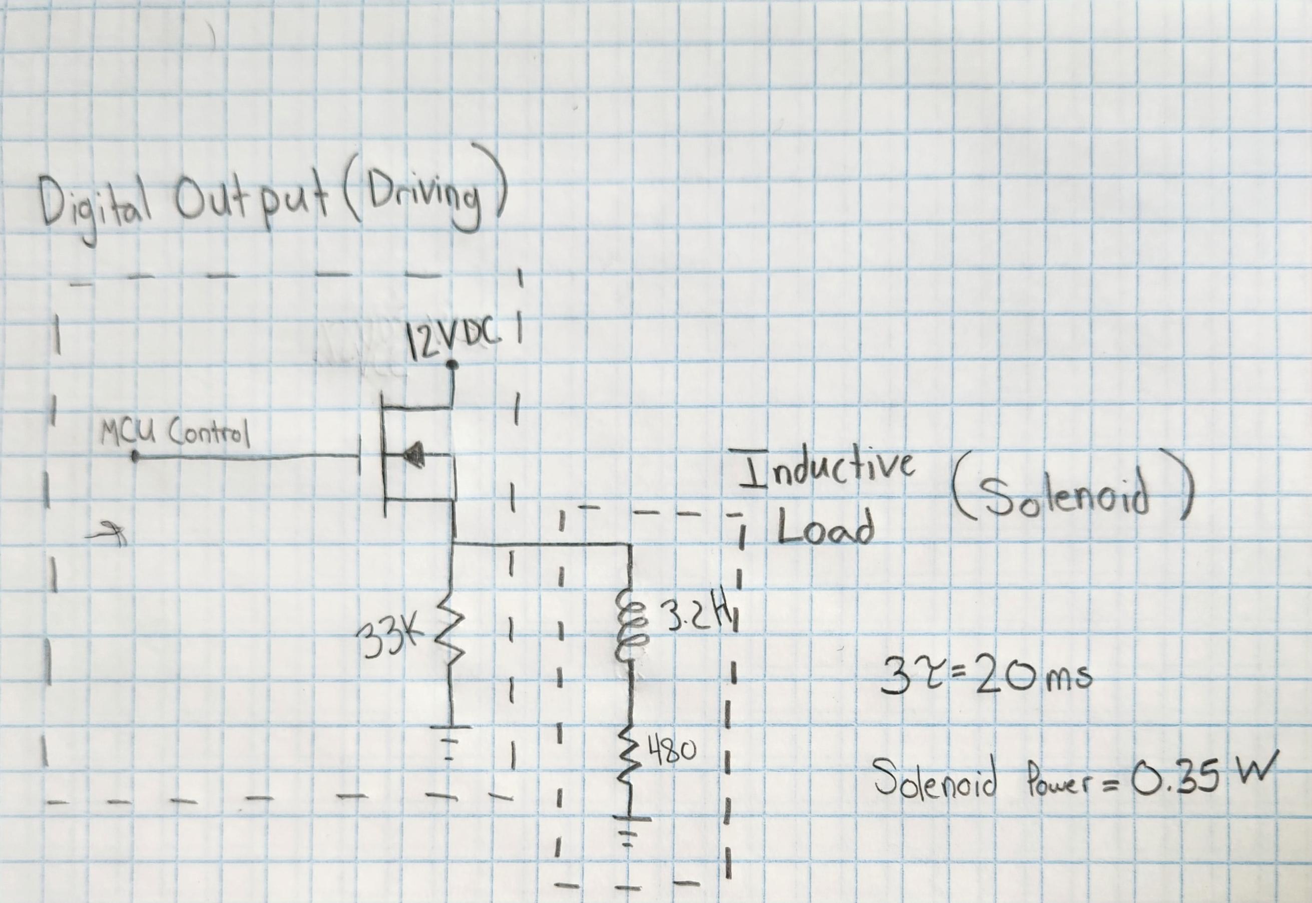
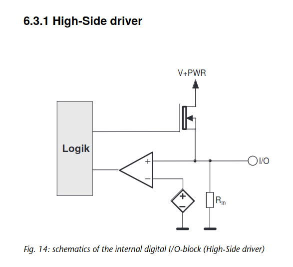
What are the effects of the pull-down resistor (33K) when the solenoid-valve enters its turn-off phase? Will it prevent the solenoid-valve from ever discharging because current would flow from ground through the pull-down resistor to the solenoid-valve? How do we protect the mosfet (e.g. clamping) when the solenoid is in the turn-off phase? If Ids Max is 2A and the solenoid IPeak was 25mA (derived from 0.35W solenoid spec), should I even be concerned about protecting the mosfet during the turn-off phase? The solenoid-valve RL circuit is modeled after a turn-on time of 20msec and it being powered at 0.35W.


-
2\$\begingroup\$ Why are you using a source follower NFET here? Do you have a datasheet for the relay? (Just curious about it.) \$\endgroup\$– periblepsisCommented May 4, 2023 at 19:02
-
1\$\begingroup\$ Agree with previous comment. Do you have a datasheet for the solenoid? The problem with this arrangement is that the FET may not stay ON as the voltage across the load increases. \$\endgroup\$– TroutdogCommented May 4, 2023 at 19:08
-
\$\begingroup\$ @Troutdog see above edits. I've attached the MCU diagram. There's really no electrical datasheet for the solenoid. I've just modeled it after the fact that it has a 20ms response time and requires 0.35W to operate. \$\endgroup\$– user2063586Commented May 4, 2023 at 19:36
-
\$\begingroup\$ I suppose the 20ms includes the reaction time of the mechanical parts of the solenoid, not just the electrical inductance, so it's probably lower than your estimate. (No problem, though) \$\endgroup\$– Criticizing Israel not allowedCommented May 4, 2023 at 19:42
-
1\$\begingroup\$ Your driver circuit is fundamentally wrong in the way you have used your MOSFET. It's a source follower and you'll be lucky to get 2 volts out of the source when the MCU drives 3.3 volts. You might get 3.5 volts out if the MCU drive level is 5 volts so, there's no need for a 12 volt supply because, and trust me on this, you'll get nowhere near 12 volts at the source, not in a hundred years. There is absolutely no-chance that you can drive 25 mA into your solenoid with that circuit. \$\endgroup\$– Andy akaCommented May 4, 2023 at 20:04
2 Answers
What are the effects of the pull-down resistor (33K) when the solenoid-valve enters its turn-off phase?
It is in parallel with the coil, so will serve to discharge the current in the coil.
Will it prevent the solenoid-valve from ever discharging because current would flow from ground through the pull-down resistor to the solenoid-valve?
No, it will help discharge the solenoid in a more controlled manner.
Without it, the solenoid will discharge even faster, but produce a much higher reverse peak voltage when shut off.
With a lower value such as 1k, the solenoid will discharge slower, but produce a much smaller reverse peak voltage when shut off.
How do we protect the MOSFET (e.g. clamping) when the solenoid is in the turn-off phase?
If speed is not an issue, then a garden-variety 1N400x diode is used instead of a resistor. This makes the coil open very slowly, but blocks the peak reverse spike to -0.7V or so.
If Ids Max is 2A and the solenoid IPeak was 25mA (derived from 0.35W solenoid spec), should I even be concerned about protecting the MOSFET during the turn-off phase?
Absolutely. The inductance is stated as 3.2 Henries, which is a fair amount of inductance. Such an inductor could make spikes in the kilovolts range. Without some means to clamp that spike, it will destroy the MOSFET.
-
\$\begingroup\$ I see 3 point 2 henries \$\endgroup\$ Commented May 4, 2023 at 19:41
-
\$\begingroup\$ It's 3.2H. It's derived the following way: 3tau = 20ms -> 3L/R = 0.02. R is assumed to be 480 from the fact that the solenoid is 0.35W, so steady state current draw will be at 25mA \$\endgroup\$ Commented May 4, 2023 at 19:43
-
\$\begingroup\$ Thanks, been squinting at tiny parts all day and eyesight is not what it used to be. Neither is brainpower either, apparently. :) \$\endgroup\$– rdtscCommented May 4, 2023 at 20:05
When the MOSFET is turned off (gate voltage presumably goes to 0V) the solenoid will continue to draw 25mA at whatever voltage that ends up being.
I calculate that the 33K resistor could develop up to 825 volts across it (that is 25mA times 33000 ohms). If the resistor were the only current path this voltage would surely destroy the MOSFET. You might even get a small arc somewhere.
However, the other path is through the MOSFET. If the gate is at 0 volts and the threshold voltage is - let's say - 3 volts, the source can go down to -3 volts and then the MOSFET turns partially on. This won't destroy the MOSFET, however it will dissipate the turnoff current. Again using the 3 volt threshold example, it would have to be able to dissipate up to 15 volts (12 + 3) times 25mA which is 0.375 watts.
Not a huge amount, so no additional protection is needed.
If the MOSFET is inside the microcontroller I would not rely on it to work this way as you don't know the exact circuitry inside the microcontroller, but you indicated that it's a separate MOSFET so it should be okay.
However, dissipating the 12 volts is an unnecessary waste of power. It's probably acceptable, being a small fraction of a joule of extra waste each time the solenoid turns off, but it can be avoided if the output's voltage is clamped to above the negative threshold voltage (e.g. by the usual clamping diode).
A quick Falstad simulation agrees with me.
-
\$\begingroup\$ Can the clamping diode be implemented on the MOSFET? I'm planning on reaching out to the manufacturer to ask about the MOSFET. I'm just not sure if I should expect a clamping diode to be present in this device as it's not demonstrated in their simple schematic. \$\endgroup\$ Commented May 4, 2023 at 20:15
-
\$\begingroup\$ @user2063586 it would be connected between ground and the output, therefore it cannot be part of the mosfet. \$\endgroup\$ Commented May 4, 2023 at 20:16
-
\$\begingroup\$ If they had an internal diode connected in this fashion, would that be sufficient? \$\endgroup\$ Commented May 4, 2023 at 20:18
-
\$\begingroup\$ Is the clamping diode the same as the flyback diode? E.g. if I have a diode in parallel with the solenoid, will this clamp the output voltage? I'm use to low-side switching, so I wasn't really sure what the considerations are for high-side switching. \$\endgroup\$ Commented May 4, 2023 at 20:24
-
\$\begingroup\$ @user2063586 It's the same thing as the flyback diode (different word, same thing), and your circuit doesn't have one \$\endgroup\$ Commented May 4, 2023 at 20:57
