Well, I don't have an intact MOT on hand to measure, but I can make some assumptions, and give some general ideas.
The short answer:
Measure it yourself, run the simulation, and see. It's a fairly simple* exercise.
I think, the simplicity of the request, combined with the somewhat poor focus or ambiguity, has led to a lack of answers (at time of writing).
*If one knows the theory and practice. But if not -- that would be the problem, wouldn't it?
So, perhaps it's worth exploring that theory and practice, so that one can be properly equipped to do that task.
First, since I don't have a transformer handy, I'll calculate the parameters from an approximate recollection of dimensions.
Then I'll explain why the design was chosen for this application.
Finally, I'll explain when you might and might not want to use the same design.
Typical Parameters

Oh, just realized I drew that as an E-E core, but it's normally E-I. Oh well, it's not important for the problem.
Typically there is a primary winding (red, P), somewhat smaller, then magnetic shunts MS, then a secondary winding (blue, S), somewhat larger. There's a filament winding in there as well, usually on the secondary side I think; it's small and not important to the problem here.
Typical dimensions might be, say, w = h = 50 mm, ws = 8 mm, lgs = 0.5 mm, and Np = 120 t (for a 120 V, 60 Hz model).
The effect of the shunts is to increase leakage inductance between primary and secondary.
Basic Transformer Design
As an introduction, suppose secondary is open-circuit, and the shunts are removed. The primary then sees the full magnetizing impedance of the core, and primary and secondary are closely coupled.
The product wh = 2500 mm2, the cross-sectional area of the center peg around which the windings are wound, is Ae, the effective area of the core.
For sine wave excitation, we use:
$$ B_\textrm{pk} = \frac{V_\textrm{rms}}{\sqrt{2} \pi F A_e N} \tag{1}$$
We find Bpk is about 1.5 T. Silicon steel ("electrical steel" or "transformer iron") typically saturates at 1.2 T or so; this is well into saturation, so large peaks of current will be drawn at the input. Which meets the observation: typically these transformers draw about as much magnetizing current (mostly harmonics!) as they do load current.
Without shunts, the secondary will receive largely the same voltage, or in this case about 1 V/t. To reach say 2500 V, 2500 t are required. This will be in much thinner wire. Usually the secondary is a bit larger (in overall volume), which may account for insulation or packing density in the winding, or for the reduced voltage after including shunts (see below).
What the Shunt?
To introduce the magnetic shunt, consider the secondary-shorted case.
With the secondary shorted, no flux gets down to the bottom. The core looks more like a single E piece with the shunts closing the loop (instead of another E as in the diagram). The bottom half might as well not exist -- it could just as well be sawn off completely, or shielded by a solid slab of metal below the shunts (which is what the shorted secondary is acting as).
The shunts act in parallel with each other, so their effective area is 2wsh. The shunts are wrapped with insulation, giving an air gap between them and the main core, lgs. The gaps act in series, so we can mentally shift the shunts towards the center, joining them with the center leg, leaving a gap of 2lgs to the outer limbs.
The air gap acts to reduce the inductance. For this we use,
$$ A_L = \frac{\mu_0 A_e}{l_g + \frac{l_e}{\mu_r}} \tag{2} $$
le is the effective length of the core, here in the ballpark of 300 mm (for the full perimeter). We can assume a μr of 5000 or so for the core below saturation, but this will decrease rapidly as it saturates. For now, we consider the linear case, and simply make note of at which point it fails (nonlinearity takes over).
Here, we use lg = 2lgs and Ae = 2wsh, and since μr is so large, we can ignore it (it's adding 0.06 mm of effective air gap, or actually about half that to the position of the shunts).
(An explanation of these relations can be found in any text on magnetic design, by the way; further explanation is out of scope here. Mind that you may find different constants (\$\sqrt{2} \pi\$ is often written 4.44) or unit multipliers (especially random powers of 10 due to use of cgs units, or worse in even older texts). I use mks units here, which are consistent: simply enter whatever numbers and their multipliers, and out drops the answer.)
AL has units of inductance per turn squared; multiply by turns squared to get the inductance. Evidently LP = 14.5 mH. Pretty low for mains operation (that's 5.5 Ω reactance, or 22 A magnetizing current!), but considering that's in a short-circuit condition, that's pretty modest! Assuming it's still valid (linearity hasn't been violated), of course.
Now, validity. Apply relation (1) again. We have Ae = 800 mm2, and get Bpk = 4.7 T. Oh well that's not good, that's considerably higher than the 1.5 T we calculated earlier. What gives?
Note that the core has two cross-sections in this configurations. The main core is still just as thick as ever, but the shunts are much thinner. They're not made to handle the full flux density! Indeed, if we take 1.2T as the limit, then we're 3.9 times outside the linear range. In other words, the shunts will give the expected (14.5 mH) inductance up to about 5.6 A, and saturate beyond there. For secondary-shorted operation, that is.
What happens above saturation? The shunts do less and less; the air gap effectively widens. This sharply reduces the primary inductance, and more current flows. So we expect the MOT will behave like a normal transformer once we get some current flowing through/across it; normal in the sense that, if we short the secondary, we draw ~fault current through the primary. (Maybe not mains-shorted levels of fault current, but one or two hundred amperes easily enough.)
Note that, if we apply this relation to the initial case (secondary open, no shunts), we get a much higher inductance: about 750 mH (or 283 Ω reactance, or 0.42 A current draw). This will be valid up to, again, 1.2 T -- but we calculated an actual 1.5 T at 120 V, so we only expect this impedance at up to 96 V. (Again, higher voltages cause the current waveform to go peaky, as the core is driven into saturation near the voltage zero crossings.)
The Magnetic Circuit
We can generalize the two above cases, and solve for overall behavior. But we need to account for the effect of the shunt on secondary output voltage, first.
We can calculate the effect of the shunts by drawing an equivalent circuit. Basically take the diagram, face-on (the figure-eight shape of the EI core), and convert core (and air gap) segments to resistors, and windings to either flux or MMF sources. We are solving for the flux through a given loop, or the MMF between a pair of nodes. Flux gives the flux density in that part of the core, and the applied voltage on respective windings; MMF gives the current flow through the winding.
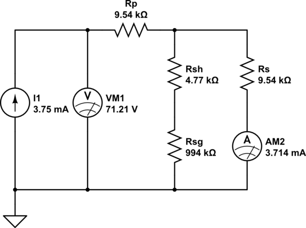
simulate this circuit – Schematic created using CircuitLab
Note that I have simplified the circuit already, by collecting series core segments, and reducing the symmetry (notice a figure-eight can be folded in half to make a single loop of twice the thickness). Rp is reluctance of the primary side main core loop (one E), Rsh the shunt (core material), Rsg the shunt air gap, and Rs the secondary side main core loop (other E).
Primary is powered, hence I1. Secondary is open, hence no current is added, but its current flow is measured (AM2).
Note that current in this analogy corresponds to winding voltage (actually flux, but we're operating at fixed 60 Hz so this is proportionate), voltage corresponds to winding current (actually MMF (magnetomotive force) \$NI\$, so divide by turns to get winding current), and resistance corresponds to reluctance.
Thus we apply a flux of \$\frac{(120 V)}{\sqrt{2} \pi (60 Hz) (120 t)} = 3.75m\$ (real unit: Wb ≡ Vs), draw a primary magnetization of 71.21 At (or 0.41 A through 120 t; again, at 120 V, assuming linearity -- as discussed earlier, this assumption only holds true up to about 96 V), and develop 3.714m flux at the secondary (or about 1% less than the primary, or 2475 V across 2500 t).
This is a small adjustment, so it seems we can happily assume an open-circuit voltage ratio equal to the turns ratio. That's handy.
What happens as we load the secondary? Its voltage drops, and more flux crosses the shunt. Suppose the secondary has 100 mA drawn on it. Here is the equivalent circuit:
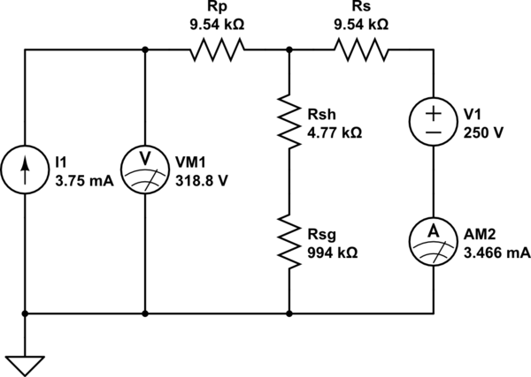
simulate this circuit
The added voltage source corresponds to the 250 At of MMF, and we see the secondary flux has decreased to 3.466 mWb, or 2308 V on the winding. Evidently the output impedance is (2475 V - 2308 V) / (0.1 A) = 1.66 kΩ, or 4.42 H (secondary referred). This is in the ballpark of the 14.5 mH (primary referred; 6.3 H secondary referred) figure found earlier, though far from exact, likely due to hand-waving the secondary-shorted equivalent circuit.
Thus, it seems a typical transformer will have an equivalent circuit something like this:
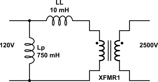
simulate this circuit
Since leakage is small, a more complete model isn't required (a tee or pi network is accurate, splitting either LL or Lp into primary- and secondary-referred halves -- the resulting inductor divider gives the voltage loss due to adding the shunt), and this will suffice for further modeling.
To measure these parameters, simply measure the inductance of the primary with the secondary unloaded, and then shorted. Preferably, do this at or near 60 Hz, and at some signal level -- some tens of volts, say. (You will find much lower inductances at low voltage, because steel has a low initial permeability i.e. at small field strength. Measurements at some kHz will also be invalid, for several reasons.)
Obviously, measuring leakage in this way could draw quite some current; a current-limiting resistor or inductor might be prudent, as well as a range of lower voltage sources (say, use a 6.3 or 12V transformer, or variac).
Leaky Transformers
Why is this design used?
The magnetron, in the forward direction, acts like a zener diode in the reverse direction. It is a vacuum (thermionic) diode, biased with an axial magnetic field, causing electrons to orbit the cathode rather than flowing directly (radially outward) to the cylindrical plate. For low applied voltages, these orbits wrap around tightly, and return to the cathode: little current flows. Only once enough voltage is applied, do electrons finally spiral out to the plate and close the circuit. Thus above a threshold voltage, significant current flows. (The orbital electron beam then passes in front of resonator cavities, like air blowing over a whistle, and thus microwave oscillation occurs.)
If we wired such a device to an ordinary transformer, depending on line voltage, it would draw either very little if any current (voltage below threshold), only at the peaks (resulting in low power factor), or extremely high (blowing the fuse, if not the device as well). Some means of limiting power or current flow is mandatory.
If we connected a resistor in series with the secondary, we could limit current, but the resistor will dissipate significant power. To get current to flow over a large part of the AC waveform, we need a much higher peak voltage (say the magnetron conducts at 3 kV, we'd want more like 5 kV peak), but then we waste much of the dropped voltage -- and at the highest currents too, giving quite poor efficiency.
If we use an inductor or capacitor instead, reactive power is dissipated, which absorbs energy during part of the cycle, and returns it later.
We can integrate inductance into the same transformer, making this an attractive option.
We can further save secondary voltage, by using a bit of cleverness with the circuit. We use a coupling capacitor and, because the magnetron only conducts one way, a clamp diode to prevent the capacitor from charging up one way. Which has the added effect of approximately doubling the output voltage (instead of peak, the magnetron sees peak-to-peak voltage).
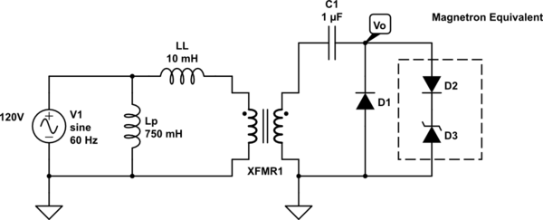
simulate this circuit

These values probably aren't too representative, as a peak current of over 2 A implies over 6 kW peak power (averaged over the half-wave waveform, probably more like 2 or 3 kW), but it's in the right ballpark. Of note, magnetron conduction is nearly 180°, which it seems the limiting effect has done its job. And as a reactive element, no extra power has been dissipated.
By probing around this simulation, you will find the voltage drop on the leakage inductor is fairly modest, hence relatively little flux is forced into the magnetic shunts -- this is why they can be thinner than the full core cross-section -- and it seems the secondary is not quite resonant. (4.42 H resonates with 1 µF at 75 Hz, suggesting we might get a bit more voltage gain for free by shifting closer to resonance, and perhaps this can be used to improve input power factor further by resonating with magnetizing inductance too. Resonance is tricky, because the effective (cycle-averaged) load resistance decreases with increasing amplitude, meaning resonance becomes stronger as it becomes stronger; we need at least enough voltage to get it to begin resonating, but not so much, and not so strong (high Q) that it runs away.)
Other Applications
Well, obviously, anything with the same characteristics, can be used the same way.
As a fluorescent lamp (or other glow/arc discharge) ballast, it's the right idea -- but the wrong amount. These typically require much higher ratios -- higher open-circuit (striking) voltage and lower conduction voltage -- necessitating larger shunts. Which will reduce secondary voltage further, requiring a larger winding. This explains the appearance of e.g. sodium lamp ballasts, with a large secondary winding to make up the strike voltage, and a capacitor either to resonate with, or to manage input power factor.
For typical reuse applications like spot welding, the shunts might not matter very much. On the one hand, they act to reduce peak input current -- at least if they aren't saturating; perhaps this could be used to get better impedance matching, reducing input current for a given load, making it less likely to blow a fuse in use. On the other hand, that same reduction in current, likely means less current at the secondary itself, and with a relatively low power capacity already, you might not be able to spare much. (Also a good reason why often several are used together, to make up enough total capacity to do the job reliably.)
Other resources: you may find this of interest:
Reuse of Post-Consumer E-waste for Low Cost Micropower Distribution

