TL;DR:
- The design is not faulty.
- Products may exist that will take a random collection of grossly differently charged cells and balance them in a single pass with the accompanying charger set at its full charge settings, but this is not one of them, and it is not designed to be.
- The BMS will not instantly balance cells which are grossly mismatched.
When building a battery pack from individual cells "standard procedure" is that all cells should be of the same type, they should all have the same "history" of use, and all should be at the same state of charge.
- This BMS will correctly balance a collection of grossly imbalance cells IF the accompanying charger is set to a charge rate less than the balancer capacity.
__________________________
Today (January 2024) I received 6 of the LiFePO4 version and 4 of the LiIon version of these BMS modules from China. That makes your question, and a good answer, of more interest to me than to most people :-). So -
How is this module supposed to balance these cells?
The issue is not so much that the BMS is faulty or that the design is bad, but that the design has limitations due to the cost/complexity tradeoffs that have been made. The limitation that you raise is unimportant if the aim is to ensure that initially well balanced cells stay that way.
For large imbalances it happens that the issue that you raise can (probably) be simply and easily addressed.
It's important to note that the DW01C (or equivalent part) achieves over and under discharge control and plays no part in the balancing. You show that you know this, but it's important to an understanding of the overall operation.
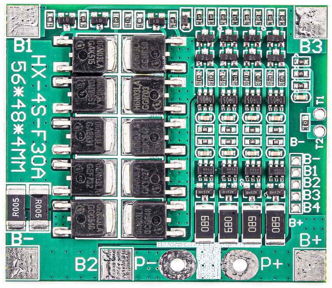
Also, it's not obvious without a circuit diagram (and / or having a module at your right hand as you type, as I do), that the large FETs are NOT equipped on a per-cell basis but, rather, all the N channels are in parallel and all the P channels are in parallel. The H6N03LA N CHANNEL FETS (datasheet here ) and equivalent P channel ones are rated at about 50A continuous with an infinite heatsink. The limit here is mainly the achievable heatsinking. [My versions use different FETs but with similar ratings.]
Rdson is around 10 milliohms, so with 5 in parallel the track and any connector resistances probably predominate.
[My units are rated at a nominal 30A. At 30A/5 = 6A per FET dissipation is notionally I^R ~= 0.4 W/FET. With 10 in proximity the 4W dissipation may be tolerable.]
To first answer your main question, the module will balance the battery if you
Charge it until it stops charging as described above.
Discharge the battery 'somewhat' until the most charged cell's voltage drops below 4.2V.
Now, charge the battery at a current lower than the rated balance current - in this case about 60 mA.
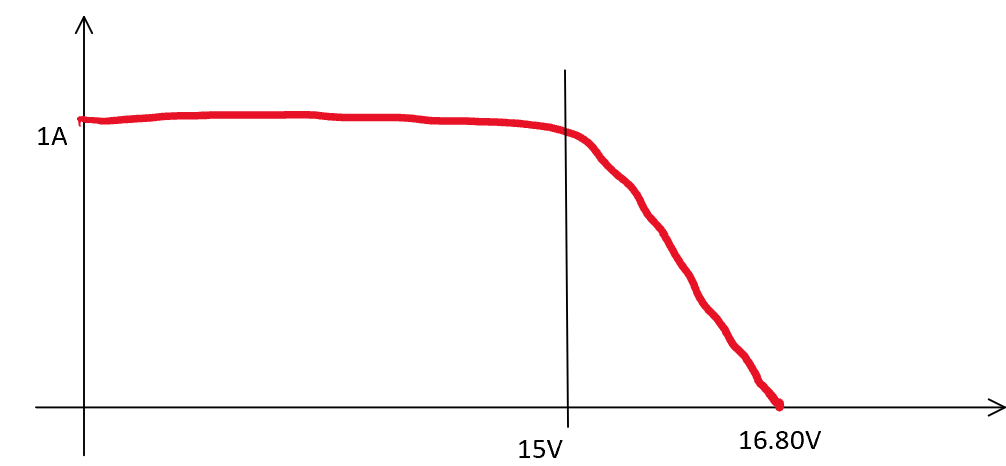
In designing a BMS like this one there are compromises between cost, capability and so complexity. The BMS IS intended to be used with a charger and is NOT intended to be used without an accompanying charger. In this case, one thing that the charger will do is limit total battery voltage to 4 x Vcell_max - usually 4 x 4.2V = 16.8V. You are correctly matching this with your " ... connect it to a 16.8 V power supply with current limited to max 500 mA" power supply".
If all cells are reasonably well but not completely balanced then as one cell reaches 4.2V the battery as a whole will be close to entering the CV portion of its CCCV charging cycle, and the most charged cell will be requiring CV balancing. At 4.2V the cell will not stop drawing current BUT the now active discharger will reduce charge current for that cell from Icc to Icv-Idischarge = 500-60 = 440 mA. The cell will be held initially at 4.2V by the discharge and as it is starting down it's CV current tapering it will for a short while tend to stay at 4.2V.
IF the other cells are 'not too far behind" they will 'soon' afterwards reach 4.2V and also enter what should be the CC phase. As the charger (in this case power supply) is set to 16.8V the battery as a whole will be in CV mode, current will begin to decrease, and all will be well.
However, in your case you suggested starting 3 cells at Vcell = 3V and one at 4V. This is so immensely out of balance that the inevitable result is the most charged cell's voltage shortly recommencing rising until the overvoltage protection shuts down the whole pack, as you observe.
The only way to achieve balance would be to shunt 100% of the charge current from the most charged cell. In this case that's 500 mA and Rdischarge would be <= 4.2V/500 mA = <= ~ 8.4 Ohm at a dissipation of 4.2 Vx 500 mA = 2.1 W. That is entirely doable. Surprisingly, the existing discharge FETs are probably adequate to the task. The FETS labelled SH2B are S12303 (datasheet here ) rated at 20 V,2.8A max, 600 mA continuous and, crucially, about 70 milliohm Rdson. Dissipation at 500 mA = I^2R = 0.5^2x 0.070 ~= 20 milliwatts (!!!).
So, replace the discharge resistors with say 8 Ohm 5 Watt parts (probably offboard and immediately adjacent) and it may balance even your immensely imbalanced example.
Superb analysis
Here - "Lithium Ion Battery Management and Protection Module (BMS ) Teardown - Schematics, Parts List and Working" is an immensely detailed, competent and useful analysis of the BMS in question. He does not really comment on the limitations that you are asking about, but his explanations demonstrate that the designer chose not to address the extreme cases that they represent.

Here is one "channel" of the BMs showing the DW01C (or equivalent) at left controlling a shared-with-all-channels over/under discharge shutdown mechanism, and at right the completely independent HY2213 balance / discharge control IC. Replace R40 for an 8 Ohm 3W (5w safer) resistor and it will (probably) balance anything at 500 mA max charge or rest.
 Beside charge controlling it is supposed to balance cells and this is where my issue emerges. If I put some unevenly charged cells in the pack, lets say 3 cells at 3 V and one at 4 V, and connect it to a 16.8 V power supply with current limited to max 500 mA. Cells will charge till the cell that initially was at 4 V reaches 4.2 V (HY2213-BB3A overcharge detection voltage). In this point the balancer activates and discharges this cell at 60 mA. But since charging current is way more than that, charging continues till this particular cell reaches 4.25 V (the DW01 Ics overcharge protection voltage). At this moment, the DW01 IC stops the charging current and the balancer drains this cell till it drops back to 4.19 V (HY2213-BB3A overcharge release voltage). But this voltage is not yet low enough for the DW01 IC to release and let the charging process continue (DW01's overcharge release is at 4.05 V).

