0
\$\begingroup\$

I'm trying to build a tachometer using a hall effect sensor which will later be an input for an Arduino. At this stage I'm still just bench testing the sensor. I bought the sensor on ebay, the listing reads that this is a 44E variant. The sensor has 3144 243 printed on it.

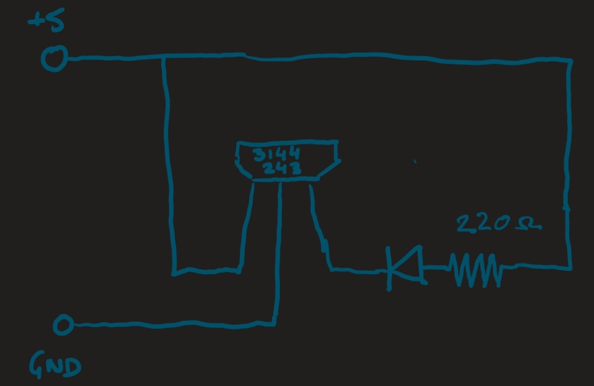
I wired the sensor according to the data sheet, but couldn't see any voltage at the signal output with or without a magnet by the sensor. Then I saw an online thread that says the signal output is high or low relative to positive. So I tried the following circuit. Now the signal wire does go high or low, lighting the LED as I move a magnet around. However the LED stays on or off even once I move the magnet away, only changing state if I move the magnet back towards the sensor with the opposite magnet pole first.

  1. Why is the signal not relative to ground as the data sheet says it should be?
  2. Should the state revert once the magnet is moved away without having to flip the magnet around?

enter image description here

\$\endgroup\$

1 Answer 1

1
\$\begingroup\$

The sensor has an open collector output. Simplified, this can be considered as a switch between GND and the output. So a load must be connected to a voltage above GND and current flows into the output in active state.

This sensor family has two magnetic threshold levels, one to turn the output on and a lower one to turn it off again.

I agree, from the datasheet I would expect, that the output is off without a magnet. An explanation could be, that there are other magnetic items around the sensor like big metal plates or even screw drivers.

The pins of the chip are made of steel. If you touch them with a magnet, there can remain a small magnetic field. This could keep the sensor active.

\$\endgroup\$

Your Answer

By clicking “Post Your Answer”, you agree to our terms of service and acknowledge you have read our privacy policy.

Not the answer you're looking for? Browse other questions tagged or ask your own question.