I'm currently working with a simple 555 variable frecuency aestable circuit, that switches a relay at the desired frecuency.
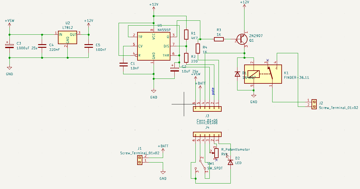
Here is the schematic so you can understand my issue better:
 The circuit is quite simple. J1 should have a 12v battery connected to it, and depending on the state of the SW1, power can go to the 7812 or directly to the relay. This is because when the switching has to stop, the relay has to stay energized, and I figured that by "unplugging" the 7812 and the 555 I would be able to "reduce" energy waste. Now, the rest of the circuit is self explainatory: The 555 switches on or off the PNP transistor at the desired frecuency (selected by the potentiometer) and as a bonus feature, an LED lights up when the relay is de-energized.
The issue is the next: Whenever SW1 is "OFF", the LED should stay static (on or off, it dosent matter), but instead, it keeps oscilating. I can still tune the frecuency using the potentiometer, and as soon as i switch SW1 to the "ON" position, everything goes back to normal working order.
I've tried to figure out by my own why could it be. I started looking to the LED, and noticed that maybe, by having the LED connected directly to the battery instead of the 12v regulated (to reduce wire count on the connector) may be having some effect on the 555 circuit (like a reverse power or something). What was a bit more concerning is that i took a look at the "12v" line, and saw, with my multimeter, around 12v, but with some fluctuation. When i cranked up the frecuency to the max (30 something Hz) the voltage got more stable, and lower. Its there, that i decided out of curiosity, to measure the voltage at the input of the 7812, and saw around 5v, which for me, makes absolutely no sense.
Now, I would like to make "reverse power" go away, but I dont know what to do/add/cut(yes, i already did the pcbs). I attached a video of the circuit working and reproducing the issue.


