1
\$\begingroup\$

I've challenged myself to make a custom ESP8266 (ESP12S) board. I'm having a problem I cannot decipher: The PC sees the USB device, and I can successfully upload my code through the Arduino IDE, but after the upload it does nothing. Uploaded blink and nothing happens.

I'm using a LM3940 to get my 3V3 and a FT231X for the UART.

I've put this schematic together on a breadboard, breakouts for the ESP & UART. I checked the voltage across the ESP's Vcc & Gnd: while uploading it is 3V3, afterward it drops to ~2V.

Is there an obvious fault here? Or is breadbording this just not good enough?

My suspicion is that this is a power delivery issue, so I swapped to a TPS63051 but the PC did not even recognize the device with that in place. Got 1V between the ESP Vcc & Gnd. I imagine that part really does not like to be on a breadboard, without any load it was producing 3V3 no problem.

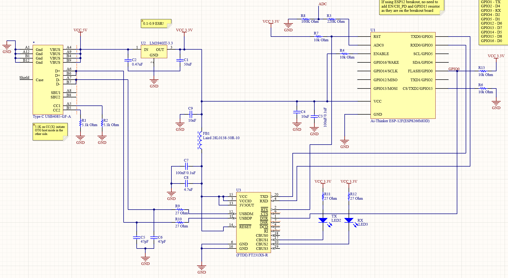
schematic

\$\endgroup\$
5
  • 1
    \$\begingroup\$ Usually the program and reset (driven by DTR, RTS) have a circuit that leaves them floating when both are high or low. Have you tried controlling the pins with a terminal program (or Python or whatever) what happens if you release the reset while the programming pin is in a state that allows the code to run? \$\endgroup\$
    – Justme
    Commented Jul 20, 2023 at 17:17
  • \$\begingroup\$ @Justme Can you share an example of such a terminal program? The UART/MCU connection was taken from a FTDI232 serial module. \$\endgroup\$ Commented Jul 20, 2023 at 20:24
  • \$\begingroup\$ For which OS? And the circuit for programming mode entry would not be in a FTDI example but in ESP8266 example and there's plenty of them. \$\endgroup\$
    – Justme
    Commented Jul 20, 2023 at 20:34
  • \$\begingroup\$ so why did you directly connect DTR to io 0? that will not work to enter/leave flashing mode \$\endgroup\$
    – Juraj
    Commented Jul 21, 2023 at 4:52
  • \$\begingroup\$ @Justme Windows, please. Juraj I was following how an FTDI USB module was wired. Upload works fine. How should it be wired? \$\endgroup\$ Commented Jul 21, 2023 at 7:19

1 Answer 1

1
\$\begingroup\$

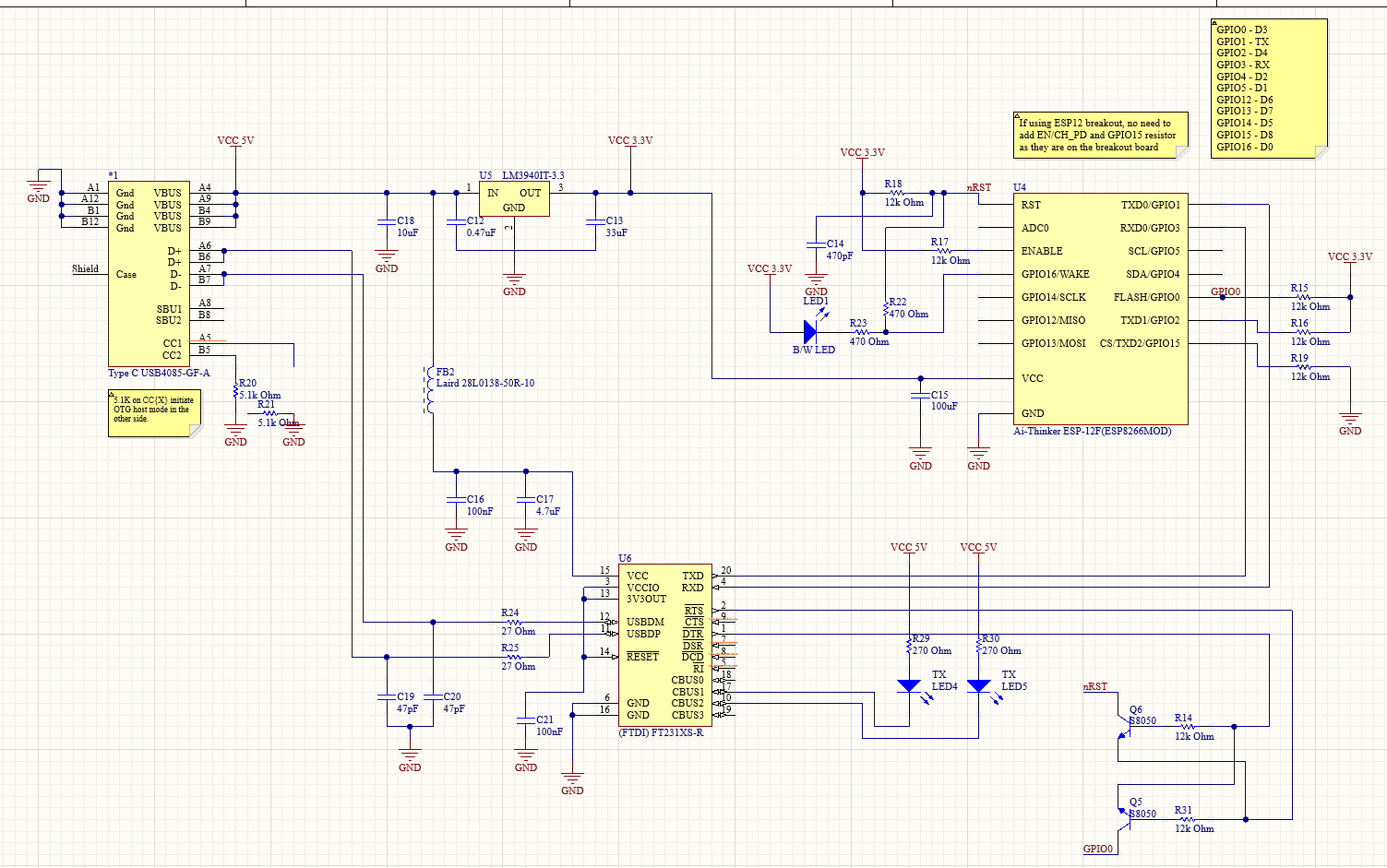
After a month of standstill, I finally figured it out. Firstly I changed the UART upload circuit to the one in the reference design. It uses a pair of transistors. I got precisely the same result - it uploads but does not boot.

Put it on a separate breadboard to check the minimum necessary for it to boot. Oddly enough it needed only Vcc and GND. Worked as expected.

Afterward, I ripped out all the connections between the MCU and UART to replicate the scenario from the other breadboard. It did not work. And then it hit me - I used a longer wire and the decoupling cap was further away.

Once I used a shorter wire & a cap right next to the MCU it all started working on the main breadboard.

final circuit

\$\endgroup\$

Your Answer

By clicking “Post Your Answer”, you agree to our terms of service and acknowledge you have read our privacy policy.

Not the answer you're looking for? Browse other questions tagged or ask your own question.