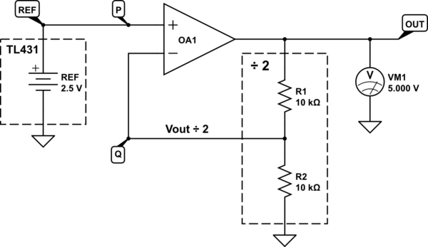
If we ignore the PWM and switching elements for the moment, here's what the system looks like:

simulate this circuit – Schematic created using CircuitLab
Your implication that the TL431 reference voltage changes as the output rises and falls is false. It stays at +2.5V regardless of the output voltage. That's its job, to maintain +2.5V at the non-inverting input of the error amplifier OA1, regardless of conditions anywhere else in the circuit.
With negative feedback provided by R1 and R2, the op-amp adjusts its output to be whatever potential \$V_{OUT}\$ is necessary to bring the potential difference between nodes P and Q (OA1's inputs) to zero. In other words, \$V_{OUT}\$ will always be maintained at the precise voltage requires to make \$V_P = V_Q\$.
Since in this example R1 and R2 produce \$V_Q=\frac{V_{OUT}}{2}\$, and \$V_P = V_{REF}=+2.5V\$, we always have:
$$
\begin{aligned}
V_P &= V_Q \\ \\
+2.5V &= \frac{V_{OUT}}{2} \\ \\
V_{OUT} &= 2 \times +2.5V \\ \\
&= +5V \\ \\
\end{aligned}
$$
Whatever load we apply to OUT, and whether that load tries to raise or lower \$V_{OUT}\$, negative feedback will cause the op-amp to work harder to restore this equilibrium where \$V_P = V_Q\$, and \$V_{OUT}=+5V\$.
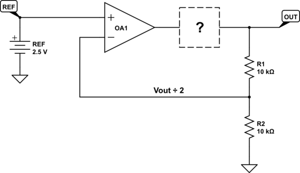
You can insert any element you like bewtween the op-amp output and the resistor potential divider (R1 & R2), and provided it conforms to certain requirements, overall behavior doesn't change:

simulate this circuit
The requirements I mentioned include having an output potential that rises when its input rises, and falls when the input falls, so that feedback always remains negative. It's more complicated that, but if you want to study this, the subject is "control systems theory", and the correlation between rising and falling inputs and outputs is called "phase shift". Additionally, the box must take a voltage as its input (since that's what OA1's output produces) and produce a voltage as an output (since the potential divider R1/R2 requires that).
In the case of a DC-DC converter, the mystery box takes a potential as its input, converts that to a PWM signal whose duty cycle varies with input potential. That PWM signal is used to switch current on and off in an inductor, current which is directed in such a way to charge a capacitor, resulting in some output voltage across the capacitor. The input to this module is a voltage, the output from this module is also a voltage, and when the input increases in potential, so does the output, and vice versa. That makes it a perfect fit for the mystery box above.
The contents of the mystery box can be an electric banana or a charge pump, or anything, as long as it has these properties. The behaviour of the error amplifier OA1 remains the same, it will adjust its own output to whatever voltage is necessary to produce the exact condition \$V_{OUT}=+5V\$. If \$V_{OUT}<+5V\$, error amplifier OA1 increases its output potential, which raises PWM duty cycle, which raises \$V_{OUT}\$. If \$V_{OUT}>+5V\$, OA1 lowers it's output, decreasing PWM duty cycle, decreasing \$V_{OUT}\$. In this way, output voltage is maintained at \$V_{OUT}=+5V\$ at all times.
For this to work \$V_P = V_{REF} = +2.5V\$ at all times, and doesn't change. If \$V_{REF}\$ changes, this alters the "equilibrium" point, and will change the value of \$V_{OUT}\$ required to achieve equilibrium. A more complete formula for the relationship between \$V_{OUT}\$, \$V_{REF}\$ and R1 and R2 is:
$$ V_{REF} = V_{OUT}\frac{R_2}{R_1+R_2} $$
or
$$ V_{OUT} = V_{REF}\left(1 + \frac{R_1}{R_2}\right) $$
This relationship holds true for any module "?", providing it meets the requirements I described above:
It takes a voltage as its input
It produces a voltage at its output
The output voltage rises when the input voltage rises, and falls when the input falls.
Update
Please allow me to explain one of the most important aspects of these "closed loop" (negative feedback) systems, it's a story I love telling, so please indulge me.
The error amplifier and the "?" box don't need to know anything about each other. The principle is that the amplifier merely adjusts "in a direction" that closes in on some desired outcome, without actually knowing what the "?" does. It's a powerful idea, that every closed loop with negative feedback operates this way, even when no element has any explicit knowledge of the behaviour of any other.
I remember clearly the day this epiphany struck me, it was almost spiritual. I was a 16 year old intern at a military weapons manufacturer, and while I understood how closed-loop systems worked in the context of inverting and non-inverting amplifiers, an engineer explained the magic to me in terms that made this principle sink deeply into my psyche.
When driving a car around a bend in the road, he said, do you know which direction you are heading? North, East? No, you don't, and you don't care. Do you know what angle you must turn the steering wheel to produce exactly the right turning rate of the car? You don't know any of this, and you don't need to. While you may understand the linkages and principles of operation of all the steering mechanisms at work, you don't need to. You could drive that car, negotiating even the most complex curves and corners, without any technical knowledge of what's happening between your hands and the road.
All you do, as the error amplifier in this scenario, is measure the difference between where you are going, and where you want to be going, and move the steering wheel in a direction to reduce that difference. And when the car is doing what you want it to, you stop adjusting.
Every system, whether it be setting the temperature of a room, weather patterns, animal populations, driving a car, when there's negative feedback to "close the loop", magic happens, stability and predictability arises, and yet no individual element of the system need care or know about any other. Things just "settle down" into some rhythm or state. To me, it is a truly astonishing principle, even after nearly 40 years.


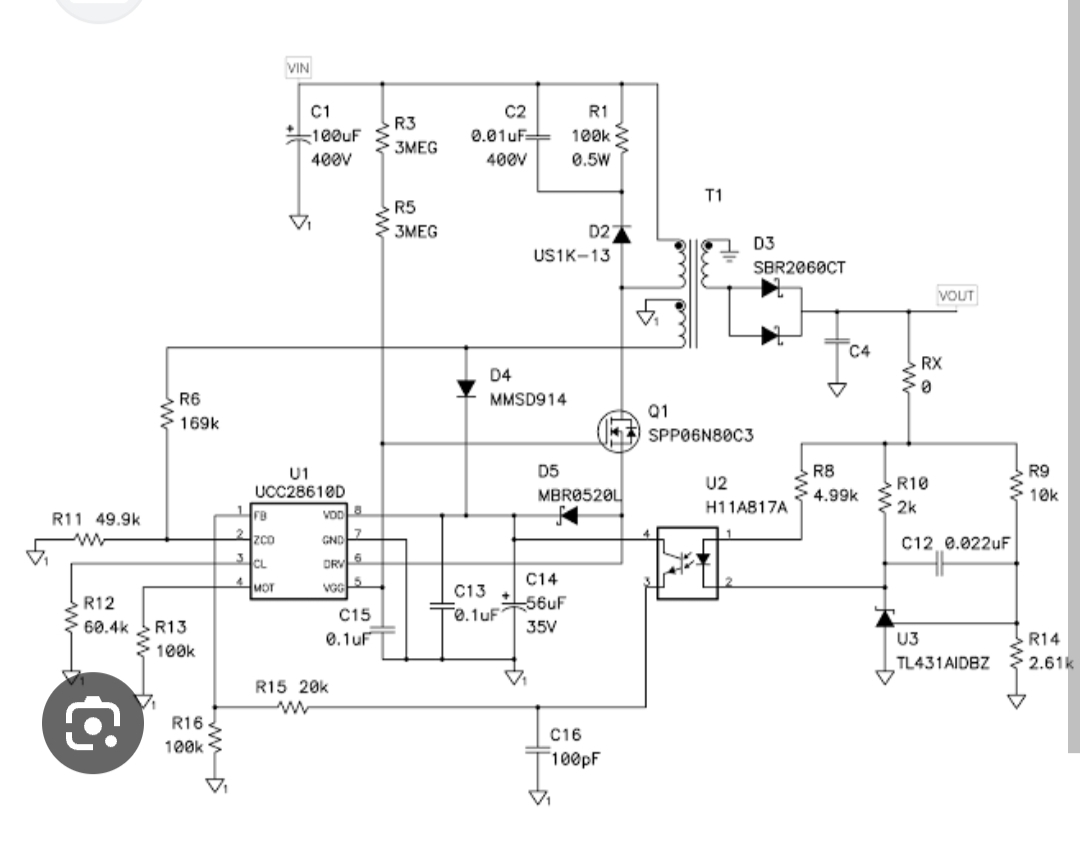
decreases to 2.3. Pictures much better than spare words and suppositions. \$\endgroup\$if I consider that the controller IC always maintains a constant 2.5V referencewhich IC? TL431 or switching controller (U1 in your schematic)? \$\endgroup\$